-
Lifting Equipment

Lifting Equipment
- Chain Hoists
-
Wire Rope Hoists & Winches
- Hand Operated Wire Rope Winches and Hoists
- Cable Pullers / Hoists, Wire Rope Manual Operation
- Electric Winches and Hoists, AC (Mains Powered)
- Scaffold Hoists & Accessories
- Overhead Wire Rope Crane Hoists
- Hydraulic Wire Rope Winches & Hoists
- Pneumatic Wire Rope Air Winches / Hoists (Lifting and Pulling)
- Vehicle Mounted Winches
- Tractel Wire Rope & Accessories
-
General Lifting Equipment
- Fibre Lifting Slings
- Chain Slings & Components
- Lifting and Lashing Chain
- Wire Rope Slings & Assemblies
- Shackles
- Eye Bolts and Eye Nuts
- Lifting & Pulling Clamps
- Lifting Beams & Spreader Beams
- Precast Concrete Lifting
- Lifting Magnets, Permanent, Battery Electric and Manual
- Runway Beam Monorail Crane Trolleys, Push, Geared & Electric
- Equipment Identification Tags
-
Rigging Equipment
- Master Ring & Load Suspension Eyes
- Lifting & Rigging Hooks
- Turnbuckles & Rigging Screws
- Wire Rope Accessories and Fittings
- Snatch Blocks, Sheave Blocks and Crane Pulley Blocks
- Pulley Sheaves
- Lifting & Rigging Swivels - Eye, Hook & Shackle
- Load Restraint Equipment
- General Rigging Accessories
- Crosby Lifting & Rigging
-
Cranes & Gantry Systems
- Portable Davit Arms and Jib Cranes
- Swing Jib Cranes - Installed Floor & Wall Cranes
- Portable/Mobile Free-standing Swing Jib Cranes
- Aluminium Gantry Cranes
- Steel Gantry Cranes
- Fixed Steel Gantry Systems
- Shearlegs, Tripods & Quadpods
- Overhead Crane Systems
- Portable Shop-Floor/Workshop/Garage Cranes
- Counterbalance Floor, Workshop Cranes
- Scaffolding Runway Beam Systems
-
Material Handling & Jacking Equipment
- Machinery & Load Moving Skates
- Hydraulic Cylinders & Pumps
- Lifting Jacks
- Manhole Cover Lifters
- Hydraulic Pull Cylinders
- Hand Operated Pallet Trucks, Pump Trucks
- Stacker Trucks, Materials Lifts, Manual and Electric
- Genie and Counterbalance Materials Lifters
- Scissor Lift Tables
- Drum Handling Equipment
- Crane Forks
- Load Weighing Equipment - Load Cells
- Tool Spring Balancers / Load Balancers
- Platform Trucks & Trolleys
-
Forklift Truck Attachment
- Fork Mounted Man Riding Baskets
- Environment & Waste Handling Attachments
- Fork Lift Truck Mounted Drum Handling Attachments
- Fork Mounted Jib and Hook Attachments
- Fork Truck Booms & Tines
- Stainless Steel Forklift Attachments
- Forklift Truck Fork Extensions
- Multi Fork Attachments
- Fork Truck Scoop Attachments
- Big Bag Fork Truck Attachment
- Closed Base Coil Support Attachments
- Forklift Fork Protection Sleeves
- Snow Plough Fork Lift Truck Attachments
- Other Forklift Truck & Telehandler Attachments
- Specialist Lifting Equipment
- Access and Safety Related
- Workshop and Shop Floor
- Screwjacks & Actuators
-
Height Safety

Height Safety Equipment
-
Fall Arrest and Height Safety Harnesses
- General Use Harnesses EN361
- Work Positioning Harnesses EN361 & EN358
- Rope Access Harnesses
- Rescue Harnesses EN1497 & EN361
- Ladies & Childrens Harnesses
- Hi Vis Jacket/Vest Harnesses
- Welders Harnesses
- ATEX (Anti-Static) Harnesses
- Linesman Harnesses
- Oil Derrick Harnesses
- Sport Climbing Harnesses
- Tree Surgeon Positioning Harnesses
- Sit and Chest Harnesses. EN361 EN356 & EN831
- Work Positioning & Restraint Belts EN358
- Fall Arrest, Restraint and Positioning Lanyards
- Height Safety and Fall Arrest Kits
- Inertia Reels and Retrieval Blocks
- Man-riding Hoists & Rescue Winches
-
Fall Arrest & Man-riding Systems
- Fall Arrest Davit Arms & Posts for Working at Height
- Sala Advanced Davit Arm Systems and Components
- Xtirpa Confined Space Davit Arm Systems and Components
- Abtech Man-riding, Fall Arrest and Rescue Davits and Components
- Man-riding & Rescue Tripods & Quadpods
- Manriding Systems, Baskets and Chairs
- Mobile Fall Arrest Gantries, Systems & Steps
- Rope Guided Fall Arresters (Steel & Synthetic Rope)
- Temporary Horizontal Fall Arrest Lifelines
- Vertical Fall Arrest Systems Permanently Installed
- Horizontal Fall Arrest Systems Permanently Installed
- Manriding Baskets Fork Truck and Overhead Crane
- Tank Side Entry and Vehicle Fall Arrest Systems
- Suspension Seats / Bosuns Chair Working at Height
- Collective Fall Arrest Systems
- Man-Riding Sheave Blocks
- Anchorage Devices
- Karabiners & Connectors
- Rescue, Evacuation & Rope Access
-
General Height Safety Gear
- Height Safety Accessories
- Industrial & Climbing Height Safety Helmets
- Synthetic Height Safety Rope & Anchorage Lines
- Height safety Pulley Wheels For Synthetic & Steel Wire Rope
- Black Height Safety Equipment & PPE
- Hot Work Equipment. Cutting, Grinding & Welding
- Cases, Bags, Backpacks, Holdalls. Height Safety Gear
- Telescopic Extension Pole for Height Safety Applications
- Wind Energy Height Safety Equipment
- Stainless Steel Fall Arrest Equipment
-
Fall Arrest and Height Safety Harnesses
- Home
- About Us
-
Contact
Get In Touch
- Home/
- Lifting Equipment/
- Rigging Gear; Riggers Lifting Equipment/
- Snatch Blocks, Sheave Blocks and Crane Pulley Blocks/
- Snatch Blocks For Wire and Synthetic Fibre Rope/
- Tractel Snatch Blocks Pulley Sheaves/
- Tractel "EP Series" EN 1808 Man-Riding Pulley Blocks / Snatch Blocks, WLL Range from 1600kg to 4800kg
Tractel "EP Series" EN 1808 Man-Riding Pulley Blocks / Snatch Blocks, WLL Range from 1600kg to 4800kg
Wire rope snatch blocks certified for both man-riding and materials handling applications. Various suspension options.
EP Series / MRPS-4452
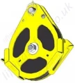


The EP series of man-riding sheaves are the only EN1808 approved sheave blocks available on the market.
Applications
- EPA/EPC/EPE/EPF/EPL pulleys are designed for man riding applications.
- Conforms to EN1808.
- Can also be used for material lifting.
- Primarily designed for temporary cable lifting or pulling applications, when quick installation and/or removal of the pulley is necessary.
- Can be fixed to a mobile or fixed anchorage point having the required WLL.
- Compatible with Tractel hoists.
- Shaves are made of black polyamide and flanges of S690Q steel.
- Colors: yellow / red / black.
Casing
- Protection of hand and fingers against trapping in the pulley groove, as required by EN 1808
- Stop detection limit for equipped hoists. Stop detection is a requirement of EN 1808 for man riding installations.
- The casings’ geometry allows using the pulley as opening pulley and facilitating wire-rope positioning.
Suspension Options
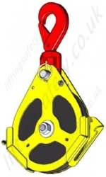
- The EPC and EPF pulleys are equipped with a safety locking hook.
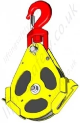
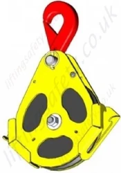
- The EPE and EPL pulleys are equipped with a hook with safety latch
 |
 |
 |
 |
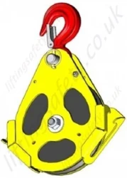 |
| EPA - Axis Only (for reduced spaces) | EPC - Swivel Self Locking Hook | EPE - Swivel Sling Hook | EPF - Fixed Self Locking Hook | EPL - Fixed Sling Hook |
Technical characteristics
- Ultimate load is 4 times the working load limit (WLL).
- The EP snatch block has been designed according to FEM 87 and EN 1808 regulations.
- The EP snatch block comes with a polyamide (PA6G) sheave and a steel body (S690 Q).
Dimensional Specifications
EP Pulleys exist in three models, with three different anchoring systems:
- EPA equipped with an axis for reduced space installation;
- EPC equipped with a swivel safety locking hook;
- EPE equipped with a swivel hook with safety latch
- EPF equipped with a fixed safety locking hook
- EPL equipped with a fixed hook with safety latch
| Model | Head Fitting | Sheave Dia. BOG* (mm) | Sheave Dia. Exterior (mm) | Wire Rope Dia. (mm) | WLL (kg) | Weight (kg) |
| EPA1.6-8/9 | Axis | 172 | 198 | 8-9 | 1600 | 2.9 |
| EPA2.4-10/12 | Axis | 196 | 219.5 | 10-12 | 2400 | 5 |
| EPA4.8-14/16 | Axis | 277.4 | 310.7 | 14-16 | 4800 | 12.2 |
| EPC1.6-8-9 | Swivel Self Locking Hook | 172 | 198 | 8-9 | 1600 | 3.7 |
| EPC2.4-10/12 | Swivel Self Locking Hook | 196 | 219.5 | 10-12 | 2400 | 6.4 |
| EPC4.8-14/16 | Swivel Self Locking Hook | 277.4 | 310.7 | 14-16 | 4800 | 14.8 |
| EPE1.6-8/9 | Swivel Sling Hook | 172 | 198 | 8-9 | 1600 | 3.7 |
| EPE2.4-10/12 | Swivel Sling Hook | 196 | 219.5 | 10-12 | 2400 | 6.4 |
| EPE4.8-14/16 | Swivel Sling Hook | 277.4 | 310.7 | 14-16 | 4800 | 14.8 |
| EPF1.6-8/9 | Fixed Self Locking Hook | 172 | 198 | 8-9 | 1600 | 3.5 |
| EPF2.4-10/12 | Fixed Self Locking Hook | 196 | 219.5 | 10-12 | 2400 | 5.9 |
| EPF4.8-14/16 | Fixed Self Locking Hook | 277.4 | 310.7 | 14-16 | 4800 | 14.1 |
| EPL1.6-8/9 | Fixed Sling Hook | 172 | 198 | 8-9 | 1600 | 3.5 |
| EPL2.4-10/12 | Fixed Sling Hook | 196 | 219.5 | 10-12 | 2400 | 5.9 |
| EPL4.8-14/16 | Fixed Sling Hook | 277.4 | 310.7 | 14-16 | 4800 | 14.1 |
* BOG = Bottom of Groove
Safety warnings
- Strictly forbidden to either be under or to walk under the load.
- Never use this block for a load exceeding its Working Load Limit (WLL). The WLL is written on the block.
Shock loading or specific conditions must also be taken into consideration when determining the product to be used. - The block should be regularly inspected (priory checking: parts correctly assembled, no excessive movement, no excessive wearing or corrosion, no deformation, no weld corrosion or cracking, free rotation of the sheave).
- Prior to using the block, check for proper position and locking of the axles. Threaded axle head should be visible after application of nuts.
- Never use a block with a hook (EPF, EPE, EPL or EPC) as head fitting without ensuring that the safety latch is correctly operated and in good condition.
- For lifting operations, the user must refer to the safety rules and regulations applicable to this use.
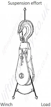
Maximal effort applied on the head fitting of the block
The maximal effort applied on the suspension depends on the load and on the α angle formed between the fall of the load and the fall on which this effort is applied.
The resultant value:
- Must be strictly lower than the working load limit of the block
and - Must be strictly lower than the resistance of the anchorage point where the block is fitted
Please refer to the table and sketch hereunder indicated:
| α angle | Effort applied on the suspension |
| 0° | Winch WLL x 2 |
| 15° | Winch WLL x 1.98 |
| 30° | Winch WLL x 1.95 |
| 45° | Winch WLL x 1.85 |
| 60° | Winch WLL x 1.73 |
| 90° | Winch WLL x 1.41 |
| 120° | Winch WLL x 1 |
| 150° | Winch WLL x 0.52 |
| 180° | 0 |
Installation
The pulley’s new design allows for easier installation.
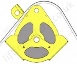 |
1. Remove the axis, shift the brace and install the cable. |
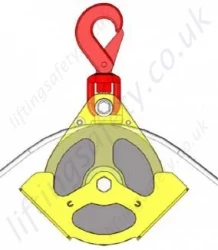 |
2. Put the brake back in place; place the axis (and the hook if the pulley is equipped with a hook). |
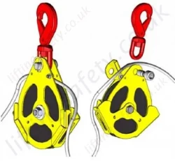 |
3. Fit the cable inside the carter through the opening. (This operation can also be done before re-installing the axis) |
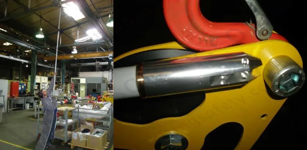
Optional Remote Installation
It is possible to install the pulley at a distance:
- Replace the security hook by a standard hook with safety latch (EPC > EPE, EPF > EPL)
- Add a threaded cap in order to insert a pole (group code 106697, sold by TSAS).
This solution is sold as a kit (designation EP-MCP, group code 192969) including threaded cap, threaded pole end, screws & bolts.
When ordered along with a pulley, it is delivered installed on the pulley.
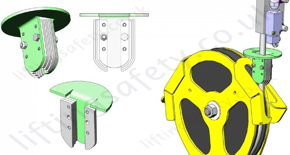
Optional Limit Detection Stop
The EP series of man-riding sheaves are the only EN1808 approved sheave blocks available on the market.
Applications
- EPA/EPC/EPE/EPF/EPL pulleys are designed for man riding applications.
- Conforms to EN1808.
- Can also be used for material lifting.
- Primarily designed for temporary cable lifting or pulling applications, when quick installation and/or removal of the pulley is necessary.
- Can be fixed to a mobile or fixed anchorage point having the required WLL.
- Compatible with Tractel hoists.
- Shaves are made of black polyamide and flanges of S690Q steel.
- Colors: yellow / red / black.
Casing
- Protection of hand and fingers against trapping in the pulley groove, as required by EN 1808
- Stop detection limit for equipped hoists. Stop detection is a requirement of EN 1808 for man riding installations.
- The casings’ geometry allows using the pulley as opening pulley and facilitating wire-rope positioning.
Suspension Options
- The EPC and EPF pulleys are equipped with a safety locking hook.
- The EPE and EPL pulleys are equipped with a hook with safety latch
 |
 |
 |
 |
 |
| EPA - Axis Only (for reduced spaces) | EPC - Swivel Self Locking Hook | EPE - Swivel Sling Hook | EPF - Fixed Self Locking Hook | EPL - Fixed Sling Hook |
Technical characteristics
- Ultimate load is 4 times the working load limit (WLL).
- The EP snatch block has been designed according to FEM 87 and EN 1808 regulations.
- The EP snatch block comes with a polyamide (PA6G) sheave and a steel body (S690 Q).
Dimensional Specifications
EP Pulleys exist in three models, with three different anchoring systems:
- EPA equipped with an axis for reduced space installation;
- EPC equipped with a swivel safety locking hook;
- EPE equipped with a swivel hook with safety latch
- EPF equipped with a fixed safety locking hook
- EPL equipped with a fixed hook with safety latch
| Model | Head Fitting | Sheave Dia. BOG* (mm) | Sheave Dia. Exterior (mm) | Wire Rope Dia. (mm) | WLL (kg) | Weight (kg) |
| EPA1.6-8/9 | Axis | 172 | 198 | 8-9 | 1600 | 2.9 |
| EPA2.4-10/12 | Axis | 196 | 219.5 | 10-12 | 2400 | 5 |
| EPA4.8-14/16 | Axis | 277.4 | 310.7 | 14-16 | 4800 | 12.2 |
| EPC1.6-8-9 | Swivel Self Locking Hook | 172 | 198 | 8-9 | 1600 | 3.7 |
| EPC2.4-10/12 | Swivel Self Locking Hook | 196 | 219.5 | 10-12 | 2400 | 6.4 |
| EPC4.8-14/16 | Swivel Self Locking Hook | 277.4 | 310.7 | 14-16 | 4800 | 14.8 |
| EPE1.6-8/9 | Swivel Sling Hook | 172 | 198 | 8-9 | 1600 | 3.7 |
| EPE2.4-10/12 | Swivel Sling Hook | 196 | 219.5 | 10-12 | 2400 | 6.4 |
| EPE4.8-14/16 | Swivel Sling Hook | 277.4 | 310.7 | 14-16 | 4800 | 14.8 |
| EPF1.6-8/9 | Fixed Self Locking Hook | 172 | 198 | 8-9 | 1600 | 3.5 |
| EPF2.4-10/12 | Fixed Self Locking Hook | 196 | 219.5 | 10-12 | 2400 | 5.9 |
| EPF4.8-14/16 | Fixed Self Locking Hook | 277.4 | 310.7 | 14-16 | 4800 | 14.1 |
| EPL1.6-8/9 | Fixed Sling Hook | 172 | 198 | 8-9 | 1600 | 3.5 |
| EPL2.4-10/12 | Fixed Sling Hook | 196 | 219.5 | 10-12 | 2400 | 5.9 |
| EPL4.8-14/16 | Fixed Sling Hook | 277.4 | 310.7 | 14-16 | 4800 | 14.1 |
* BOG = Bottom of Groove
Safety warnings
- Strictly forbidden to either be under or to walk under the load.
- Never use this block for a load exceeding its Working Load Limit (WLL). The WLL is written on the block.
Shock loading or specific conditions must also be taken into consideration when determining the product to be used. - The block should be regularly inspected (priory checking: parts correctly assembled, no excessive movement, no excessive wearing or corrosion, no deformation, no weld corrosion or cracking, free rotation of the sheave).
- Prior to using the block, check for proper position and locking of the axles. Threaded axle head should be visible after application of nuts.
- Never use a block with a hook (EPF, EPE, EPL or EPC) as head fitting without ensuring that the safety latch is correctly operated and in good condition.
- For lifting operations, the user must refer to the safety rules and regulations applicable to this use.

Maximal effort applied on the head fitting of the block
The maximal effort applied on the suspension depends on the load and on the α angle formed between the fall of the load and the fall on which this effort is applied.
The resultant value:
- Must be strictly lower than the working load limit of the block
and - Must be strictly lower than the resistance of the anchorage point where the block is fitted
Please refer to the table and sketch hereunder indicated:
| α angle | Effort applied on the suspension |
| 0° | Winch WLL x 2 |
| 15° | Winch WLL x 1.98 |
| 30° | Winch WLL x 1.95 |
| 45° | Winch WLL x 1.85 |
| 60° | Winch WLL x 1.73 |
| 90° | Winch WLL x 1.41 |
| 120° | Winch WLL x 1 |
| 150° | Winch WLL x 0.52 |
| 180° | 0 |
Installation
The pulley’s new design allows for easier installation.
 |
1. Remove the axis, shift the brace and install the cable. |
 |
2. Put the brake back in place; place the axis (and the hook if the pulley is equipped with a hook). |
 |
3. Fit the cable inside the carter through the opening. (This operation can also be done before re-installing the axis) |
Optional Remote Installation
It is possible to install the pulley at a distance:
- Replace the security hook by a standard hook with safety latch (EPC > EPE, EPF > EPL)
- Add a threaded cap in order to insert a pole (group code 106697, sold by TSAS).
This solution is sold as a kit (designation EP-MCP, group code 192969) including threaded cap, threaded pole end, screws & bolts.
When ordered along with a pulley, it is delivered installed on the pulley.

Optional Limit Detection Stop

Products of Possible Interest


Contact Us About This Product
If you wish to receive a quote for this product, please use the tab above, this form is for general enquiries regarding this product only.
You can also Request a Quote using the Quote tab above!
You can easily add more than one item to the Quote Request. This is highly recommended as we will be able to suit your needs much more efficiently.
