-
Lifting Equipment

Lifting Equipment
- Chain Hoists
-
Wire Rope Hoists & Winches
- Hand Operated Wire Rope Winches and Hoists
- Cable Pullers / Hoists, Wire Rope Manual Operation
- Electric Winches and Hoists, AC (Mains Powered)
- Scaffold Hoists & Accessories
- Overhead Wire Rope Crane Hoists
- Hydraulic Wire Rope Winches & Hoists
- Pneumatic Wire Rope Air Winches / Hoists (Lifting and Pulling)
- Vehicle Mounted Winches
- Tractel Wire Rope & Accessories
-
General Lifting Equipment
- Soft Lifting Slings
- Lifting Chain Slings
- Wire Rope Slings & Assemblies
- Lifting Shackles
- Eye Bolts and Nuts
- Weld-on Lifting Eyes and Lashing Points
- Lifting & Pulling Clamps
- Lifting Beams & Spreader Beams
- Precast Concrete Lifting
- Lifting Magnets, Permanent, Battery Electric and Manual
- Beam Trolleys and Crane Bridges, Push, Geared & Electric
- Equipment Identification Tags
-
Rigging Equipment
- Master Ring & Load Suspension Eyes
- Lifting & Rigging Hooks
- Turnbuckles & Rigging Screws
- Wire Rope Accessories and Fittings
- Snatch Blocks, Sheave Blocks and Crane Pulley Blocks
- Pulley Sheaves
- Lifting & Rigging Swivels - Eye, Hook & Shackle
- Load Restraint Equipment
- General Rigging Accessories
- Crosby Lifting & Rigging
-
Cranes & Gantry Systems
- Portable Davit Arms
- Swing Jib Cranes - Installed Floor & Wall Cranes
- Portable/Mobile Free-standing Swing Jib Cranes
- Aluminium Gantry Cranes
- Steel Gantry Cranes
- Fixed Steel Gantry Systems
- Shearlegs, Tripods & Quadpods
- Overhead Crane Systems
- Portable Shop-Floor/Workshop/Garage Cranes
- Counterbalance Floor, Workshop Cranes
- Scaffolding Runway Beam Systems
-
Material Handling & Jacking Equipment
- Machinery & Load Moving Skates
- Hydraulic Cylinders & Pumps
- Lifting Jacks
- Manhole Cover Lifters
- Hydraulic Pull Cylinders
- Hand Operated Pallet Trucks, Pump Trucks
- Stacker Trucks, Materials Lifts, Manual and Electric
- Genie and Counterbalance Materials Lifters
- Scissor Lift Tables
- Drum Handling Equipment
- Crane Forks
- Load Weighing Equipment - Load Cells
- Tool Spring Balancers / Load Balancers
- Platform Trucks & Trolleys
-
Forklift Truck Attachment
- Fork Mounted Man Riding Baskets
- Environment & Waste Handling Attachments
- Fork Lift Truck Mounted Drum Handling Attachments
- Fork Mounted Jib and Hook Attachments
- Fork Truck Booms & Tines
- Stainless Steel Forklift Attachments
- Forklift Truck Fork Extensions
- Multi Fork Attachments
- Fork Truck Scoop Attachments
- Big Bag Fork Truck Attachment
- Closed Base Coil Support Attachments
- Forklift Fork Protection Sleeves
- Snow Plough Fork Lift Truck Attachments
- Other Forklift Truck & Telehandler Attachments
- Specialist Lifting Equipment
- Access and Safety Related
- Workshop and Shop Floor
- Screwjacks & Actuators
-
Height Safety

Height Safety Equipment
-
Fall Arrest and Height Safety Harnesses
- General Use Harnesses EN361
- Work Positioning Harnesses EN361 & EN358
- Rope Access Harnesses
- Rescue Harnesses EN1497 & EN361
- Ladies & Childrens Harnesses
- Hi Vis Jacket/Vest Harnesses
- Welders Harnesses
- ATEX (Anti-Static) Harnesses
- Linesman Harnesses
- Oil Derrick Harnesses
- Sport Climbing Harnesses
- Tree Surgeon Positioning Harnesses
- Sit and Chest Harnesses. EN361 EN356 & EN831
- Work Positioning & Restraint Belts EN358
- Fall Arrest, Restraint and Positioning Lanyards
- Height Safety and Fall Arrest Kits
- Inertia Reels and Retrieval Blocks
-
Confined Space and Rescue Systems
- Xtirpa Confined Space Davit Arm Systems and Components
- Sala Advanced Davit Arm Systems and Components
- Genesi Confined Space Systems
- Abtech Man-riding, Fall Arrest and Rescue Davits and Components
- Man-riding Hoists & Rescue Winches
- Fall Arrest & Rescue Tripods
- Fall Arrest Davit Arms & Posts for Working at Height
-
Fall Arrest & Man-riding Systems
- Manriding Systems, Baskets and Chairs
- Mobile Fall Arrest Gantries, Systems & Steps
- Rope Guided Fall Arresters (Steel & Synthetic Rope)
- Temporary Horizontal Fall Arrest Lifelines
- Vertical Fall Arrest Systems Permanently Installed
- Horizontal Fall Arrest Systems Permanently Installed
- Manriding Baskets Fork Truck and Overhead Crane
- Tank Side Entry and Vehicle Fall Arrest Systems
- Suspension Seats / Bosuns Chair Working at Height
- Collective Fall Arrest Systems
- Man-Riding Sheave Blocks
- Anchorage Devices
- Karabiners & Connectors
- Rescue, Evacuation & Rope Access
-
General Height Safety Gear
- Height Safety Accessories
- Industrial & Climbing Height Safety Helmets
- Synthetic Height Safety Rope & Anchorage Lines
- Height safety Pulley Wheels For Synthetic & Steel Wire Rope
- Black Height Safety Equipment & PPE
- Hot Work Equipment. Cutting, Grinding & Welding
- Cases, Bags, Backpacks, Holdalls. Height Safety Gear
- Telescopic Extension Pole for Height Safety Applications
- Wind Energy Height Safety Equipment
- Stainless Steel Fall Arrest Equipment
-
Fall Arrest and Height Safety Harnesses
- Home
- About Us
-
Contact
Get In Touch
- Home/
- Lifting Equipment/
- Rigging Gear; Riggers Lifting Equipment/
- Crosby Lifting Equipment & Rigging Catalogue/
- Crosby Anchor Shackles (Bow and "D")/
- Crosby Bow Shackles (Omega Shackles)/
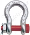
- Crosby 'G2140' Alloy Bolt Anchor Bow Lifting Shackles with Nut & Split Pin, WLL Range from 2,000kg to 400 tonne
Crosby 'G2140' Alloy Bolt Anchor Bow Lifting Shackles with Nut & Split Pin, WLL Range from 2,000kg to 400 tonne
Crosby alloy steel bolt type safety shackles.
Crosby G2140 / ABAS-2381

G-2140 meets the performance requirements of Federal Specification RR-C-271F, Type IVA, Grade B, Class 3, except for those provisions required of the contractor.
- Quenched and Tempered.
- Alloy bows, Alloy bolts.
- Forged Alloy Steel 2 thru 200 metric tons. Cast Alloy Steel 250 thru 400 metric tons. Meets performance requirements of Grade 8 shackles.
- Working Load Limit is permanently shown on every shackle.
- 30, 40, 55, and 85 metric ton shackle bows are available galvanized or self colored with pins that aregalvanized and painted red.
- 120, 150, 175 metric ton shackle bows are hot-dip galvanized; bolts are Dimetcoted® and painted red.
- 400 metric ton shackle bows are Dimetcoted®; bolts are Dimetcoted® and painted red.
- Sizes 1-1/2 and larger are RFID EQUIPPED.
- Approved for use at -40 degrees C (-40 degrees F) to 204 degrees C (400 degrees F).
- Shackles are Quenched and Tempered and can meet DNV impact requirements of 42 joules (31 ft-lbs.) at -20 degrees C (-4 degrees F).
- All sizes are individually proof tested to 2.0 times the Working Load Limit.
- Shackles 200 metric tons and larger are provided as follows.
- Serialized pin and bow.
- Material certification (chemical).
- Magnetic particle inspected.
- Certification must be requested at time of order.
- Meets or exceeds all requirements of ASME B30.26 including identification, ductility, design factor, proof load and temperature requirements. 2140 shackles meet other critical performance requirements including impact properties and material traceability, not addressed by ASME B30.26.
- Type Approval certification in accordance with ABS 2007 Steel Vessel Rules 1-11-17.7and ABS Guide for Certification on Cranes available. Certificates available whenrequested at time of order and may include additional charges
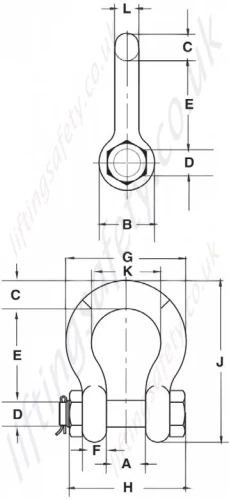
Metric Specifications & Specifications
| Nominal Shackle Size (in.) | Working Load Limit (t)* | Stock No. | Weight Each (kg) | Dimensions (mm) | Tolerance + / - | |||||||||||
| A | B | C | D +/- .5 | E | F | G | H | J | K | L | A | E | ||||
| 3/8 | 2 | 1021015 | 0.15 | 16.8 | 23.1 | 9.7 | 11.2 | 36.6 | 9.7 | 45.2 | 55.1 | 63.2 | 26.2 | 9.7 | 1.5 | 3.3 |
| 7/16 | 2 2/3 | 1021020 | 0.22 | 19.1 | 26.9 | 11.2 | 12.7 | 42.9 | 10.4 | 51.6 | 63.8 | 73.9 | 29.5 | 11.2 | 1.5 | 3.3 |
| 1/2 | 3 1/3 | 1021029 | 0.36 | 20.6 | 30.2 | 12.7 | 16.3 | 47.8 | 11.7 | 58.7 | 71.1 | 83.3 | 33.3 | 12.7 | 1.5 | 3.3 |
| 5/8 | 5 | 1021038 | 0.76 | 26.9 | 38.1 | 17.5 | 19.6 | 60.5 | 14.7 | 74.7 | 90.4 | 106.4 | 42.9 | 16 | 1.5 | 3.3 |
| 3/4 | 7 | 1021047 | 1.23 | 31.8 | 46 | 20.6 | 22.6 | 71.4 | 17.5 | 88.9 | 105.4 | 126.2 | 50.8 | 19.1 | 1.5 | 6.4 |
| 7/8 | 9 1/2 | 1021056 | 1.79 | 36.6 | 53.1 | 24.6 | 25.9 | 84.1 | 20.6 | 102.4 | 122.4 | 148.1 | 57.9 | 22.4 | 1.5 | 6.4 |
| 1 | 12 1/2 | 1021065 | 2.57 | 42.9 | 60.5 | 26.9 | 29.2 | 95.3 | 23.4 | 119.1 | 136.9 | 166.6 | 68.3 | 25.4 | 1.5 | 6.4 |
| 1 1/8 | 15 | 1021074 | 3.75 | 46 | 68.3 | 31.8 | 31.8 | 108 | 26.4 | 131.1 | 149.9 | 189.7 | 73.9 | 28.7 | 1.5 | 6.4 |
| 1 1/4 | 18 | 1021083 | 5.31 | 51.6 | 76.2 | 35.1 | 35.6 | 119.1 | 29.5 | 146.1 | 169.9 | 209.6 | 82.6 | 32.8 | 1.5 | 6.4 |
| 1 3/8 | 21 | 1021092 | 7.18 | 57.2 | 84.1 | 38.1 | 38.9 | 133.4 | 32.5 | 162.1 | 183.1 | 232.7 | 92.2 | 36.1 | 3.3 | 6.4 |
| 1-1/2 | 30 | 1021110 | 8.52 | 60.5 | 91.9 | 41.1 | 41.4 | 146 | 35.3 | 175 | 196 | 254 | 98.6 | 38.9 | 3.3 | 6.4 |
| 1-3/4 | 40 | 1021138 | 15.4 | 73.2 | 106 | 57.2 | 50.8 | 178 | 44.5 | 224 | 237 | 313 | 127 | 46.7 | 3.3 | 6.4 |
| 2 | 55 | 1021156 | 23.6 | 82.6 | 122 | 61 | 57.2 | 197 | 50.8 | 258 | 264 | 347 | 146 | 52.8 | 3.3 | 6.4 |
| 2-1/2 | 85 | 1021174 | 43.5 | 105 | 148 | 79.2 | 69.9 | 267 | 66.5 | 324 | 345 | 455 | 184 | 68.8 | 6.4 | 6.4 |
| 3 | 120 | 1021192 | 81 | 127 | 165 | 92.2 | 82.6 | 330 | 76.2 | 371 | 384 | 546 | 200 | 79.2 | 6.4 | 6.4 |
| 3-1/2 | † 150 | 1021218 | 120 | 133 | 203 | 111 | 95.3 | 372 | 95.3 | 432 | 448 | 632 | 229 | 91.9 | 6.4 | 6.4 |
| 4 | † 175 | 1021236 | 153 | 140 | 229 | 116 | 108 | 368 | 102 | 457 | 517 | 652 | 254 | 102 | 6.4 | 6.4 |
| 4 3/4 | † 200 | 1021422 | 209 | 184 | 267 | 127 | 121 | 386 | 116 | 529 | 611 | 706 | 279 | 121 | 6.35 | 6.35 |
| 5 | † 250 | 1021442 | 276 | 216 | 305 | 143 | 127 | 470 | 123 | 600 | 632 | 828 | 330 | 127 | 4 | 1.8 |
| 6 | † 300 | 1021460 | 362 | 213 | 330 | 154 | 152 | 475 | 124 | 629 | 666 | 871 | 330 | 149 | 4 | 1.8 |
| 7** | † 400 | 1021478 | 500 | 210 | 356 | 184 | 178 | 572 | 165 | 660 | 728 | 1022 | 330 | 152 | 6.4 | 6.4 |

* Note: Maximum Proof Load is 2.0 times the Working Load Limit. Minimum Ultimate Load is 4.5 times the Working Load Limit on 2 thru 21 metric tons. For sizes 30 thru 175
metric tons, Minimum Ultimate Load is 5.4 times the Working Load Limit for 200 thru 400 metric tons, Minimum Ultimate Load is 4.times the Working Load Limit.
** Cast Alloy Steel.
† Furnished with Round Head Bolts with an eyebolt for handling. For Working Load Limit reduction due to side loading applications, see page 94 ('Downloads' tab above).
Imperial Specifications & Specifications
For Imperial Dimensions and Specifications click the 'Downloads' tab above and view the 'Crosby 213 Carbon Round Pin Chain Shackles - Imperial (Page 76)' PDF.
G-2140 meets the performance requirements of Federal Specification RR-C-271F, Type IVA, Grade B, Class 3, except for those provisions required of the contractor.
- Quenched and Tempered.
- Alloy bows, Alloy bolts.
- Forged Alloy Steel 2 thru 200 metric tons. Cast Alloy Steel 250 thru 400 metric tons. Meets performance requirements of Grade 8 shackles.
- Working Load Limit is permanently shown on every shackle.
- 30, 40, 55, and 85 metric ton shackle bows are available galvanized or self colored with pins that aregalvanized and painted red.
- 120, 150, 175 metric ton shackle bows are hot-dip galvanized; bolts are Dimetcoted® and painted red.
- 400 metric ton shackle bows are Dimetcoted®; bolts are Dimetcoted® and painted red.
- Sizes 1-1/2 and larger are RFID EQUIPPED.
- Approved for use at -40 degrees C (-40 degrees F) to 204 degrees C (400 degrees F).
- Shackles are Quenched and Tempered and can meet DNV impact requirements of 42 joules (31 ft-lbs.) at -20 degrees C (-4 degrees F).
- All sizes are individually proof tested to 2.0 times the Working Load Limit.
- Shackles 200 metric tons and larger are provided as follows.
- Serialized pin and bow.
- Material certification (chemical).
- Magnetic particle inspected.
- Certification must be requested at time of order.
- Meets or exceeds all requirements of ASME B30.26 including identification, ductility, design factor, proof load and temperature requirements. 2140 shackles meet other critical performance requirements including impact properties and material traceability, not addressed by ASME B30.26.
- Type Approval certification in accordance with ABS 2007 Steel Vessel Rules 1-11-17.7and ABS Guide for Certification on Cranes available. Certificates available whenrequested at time of order and may include additional charges
Metric Specifications & Specifications
| Nominal Shackle Size (in.) | Working Load Limit (t)* | Stock No. | Weight Each (kg) | Dimensions (mm) | Tolerance + / - | |||||||||||
| A | B | C | D +/- .5 | E | F | G | H | J | K | L | A | E | ||||
| 3/8 | 2 | 1021015 | 0.15 | 16.8 | 23.1 | 9.7 | 11.2 | 36.6 | 9.7 | 45.2 | 55.1 | 63.2 | 26.2 | 9.7 | 1.5 | 3.3 |
| 7/16 | 2 2/3 | 1021020 | 0.22 | 19.1 | 26.9 | 11.2 | 12.7 | 42.9 | 10.4 | 51.6 | 63.8 | 73.9 | 29.5 | 11.2 | 1.5 | 3.3 |
| 1/2 | 3 1/3 | 1021029 | 0.36 | 20.6 | 30.2 | 12.7 | 16.3 | 47.8 | 11.7 | 58.7 | 71.1 | 83.3 | 33.3 | 12.7 | 1.5 | 3.3 |
| 5/8 | 5 | 1021038 | 0.76 | 26.9 | 38.1 | 17.5 | 19.6 | 60.5 | 14.7 | 74.7 | 90.4 | 106.4 | 42.9 | 16 | 1.5 | 3.3 |
| 3/4 | 7 | 1021047 | 1.23 | 31.8 | 46 | 20.6 | 22.6 | 71.4 | 17.5 | 88.9 | 105.4 | 126.2 | 50.8 | 19.1 | 1.5 | 6.4 |
| 7/8 | 9 1/2 | 1021056 | 1.79 | 36.6 | 53.1 | 24.6 | 25.9 | 84.1 | 20.6 | 102.4 | 122.4 | 148.1 | 57.9 | 22.4 | 1.5 | 6.4 |
| 1 | 12 1/2 | 1021065 | 2.57 | 42.9 | 60.5 | 26.9 | 29.2 | 95.3 | 23.4 | 119.1 | 136.9 | 166.6 | 68.3 | 25.4 | 1.5 | 6.4 |
| 1 1/8 | 15 | 1021074 | 3.75 | 46 | 68.3 | 31.8 | 31.8 | 108 | 26.4 | 131.1 | 149.9 | 189.7 | 73.9 | 28.7 | 1.5 | 6.4 |
| 1 1/4 | 18 | 1021083 | 5.31 | 51.6 | 76.2 | 35.1 | 35.6 | 119.1 | 29.5 | 146.1 | 169.9 | 209.6 | 82.6 | 32.8 | 1.5 | 6.4 |
| 1 3/8 | 21 | 1021092 | 7.18 | 57.2 | 84.1 | 38.1 | 38.9 | 133.4 | 32.5 | 162.1 | 183.1 | 232.7 | 92.2 | 36.1 | 3.3 | 6.4 |
| 1-1/2 | 30 | 1021110 | 8.52 | 60.5 | 91.9 | 41.1 | 41.4 | 146 | 35.3 | 175 | 196 | 254 | 98.6 | 38.9 | 3.3 | 6.4 |
| 1-3/4 | 40 | 1021138 | 15.4 | 73.2 | 106 | 57.2 | 50.8 | 178 | 44.5 | 224 | 237 | 313 | 127 | 46.7 | 3.3 | 6.4 |
| 2 | 55 | 1021156 | 23.6 | 82.6 | 122 | 61 | 57.2 | 197 | 50.8 | 258 | 264 | 347 | 146 | 52.8 | 3.3 | 6.4 |
| 2-1/2 | 85 | 1021174 | 43.5 | 105 | 148 | 79.2 | 69.9 | 267 | 66.5 | 324 | 345 | 455 | 184 | 68.8 | 6.4 | 6.4 |
| 3 | 120 | 1021192 | 81 | 127 | 165 | 92.2 | 82.6 | 330 | 76.2 | 371 | 384 | 546 | 200 | 79.2 | 6.4 | 6.4 |
| 3-1/2 | † 150 | 1021218 | 120 | 133 | 203 | 111 | 95.3 | 372 | 95.3 | 432 | 448 | 632 | 229 | 91.9 | 6.4 | 6.4 |
| 4 | † 175 | 1021236 | 153 | 140 | 229 | 116 | 108 | 368 | 102 | 457 | 517 | 652 | 254 | 102 | 6.4 | 6.4 |
| 4 3/4 | † 200 | 1021422 | 209 | 184 | 267 | 127 | 121 | 386 | 116 | 529 | 611 | 706 | 279 | 121 | 6.35 | 6.35 |
| 5 | † 250 | 1021442 | 276 | 216 | 305 | 143 | 127 | 470 | 123 | 600 | 632 | 828 | 330 | 127 | 4 | 1.8 |
| 6 | † 300 | 1021460 | 362 | 213 | 330 | 154 | 152 | 475 | 124 | 629 | 666 | 871 | 330 | 149 | 4 | 1.8 |
| 7** | † 400 | 1021478 | 500 | 210 | 356 | 184 | 178 | 572 | 165 | 660 | 728 | 1022 | 330 | 152 | 6.4 | 6.4 |

* Note: Maximum Proof Load is 2.0 times the Working Load Limit. Minimum Ultimate Load is 4.5 times the Working Load Limit on 2 thru 21 metric tons. For sizes 30 thru 175
metric tons, Minimum Ultimate Load is 5.4 times the Working Load Limit for 200 thru 400 metric tons, Minimum Ultimate Load is 4.times the Working Load Limit.
** Cast Alloy Steel.
† Furnished with Round Head Bolts with an eyebolt for handling. For Working Load Limit reduction due to side loading applications, see page 94 ('Downloads' tab above).
Imperial Specifications & Specifications
For Imperial Dimensions and Specifications click the 'Downloads' tab above and view the 'Crosby 213 Carbon Round Pin Chain Shackles - Imperial (Page 76)' PDF.
You May Also Like
Contact Us About This Product
If you wish to receive a quote for this product, please use the tab above, this form is for general enquiries regarding this product only.
You can also Request a Quote using the Quote tab above!
You can easily add more than one item to the Quote Request. This is highly recommended as we will be able to suit your needs much more efficiently.


