-
Lifting Equipment

Lifting Equipment
- Chain Hoists
-
Wire Rope Hoists & Winches
- Hand Operated Wire Rope Winches and Hoists
- Cable Pullers / Hoists, Wire Rope Manual Operation
- Electric Winches and Hoists, AC (Mains Powered)
- Scaffold Hoists & Accessories
- Overhead Wire Rope Crane Hoists
- Hydraulic Wire Rope Winches & Hoists
- Pneumatic Wire Rope Air Winches / Hoists (Lifting and Pulling)
- Vehicle Mounted Winches
- Tractel Wire Rope & Accessories
-
General Lifting Equipment
- Soft Lifting Slings
- Lifting Chain Slings
- Wire Rope Slings & Assemblies
- Lifting Shackles
- Eye Bolts and Nuts
- Weld-on Lifting Eyes and Lashing Points
- Lifting & Pulling Clamps
- Lifting Beams & Spreader Beams
- Precast Concrete Lifting
- Lifting Magnets, Permanent, Battery Electric and Manual
- Beam Trolleys and Crane Bridges, Push, Geared & Electric
- Equipment Identification Tags
-
Rigging Equipment
- Master Ring & Load Suspension Eyes
- Lifting & Rigging Hooks
- Turnbuckles & Rigging Screws
- Wire Rope Accessories and Fittings
- Snatch Blocks, Sheave Blocks and Crane Pulley Blocks
- Pulley Sheaves
- Lifting & Rigging Swivels - Eye, Hook & Shackle
- Load Restraint Equipment
- General Rigging Accessories
- Crosby Lifting & Rigging
-
Cranes & Gantry Systems
- Portable Davit Arms
- Swing Jib Cranes - Installed Floor & Wall Cranes
- Portable/Mobile Free-standing Swing Jib Cranes
- Aluminium Gantry Cranes
- Steel Gantry Cranes
- Fixed Steel Gantry Systems
- Shearlegs, Tripods & Quadpods
- Overhead Crane Systems
- Portable Shop-Floor/Workshop/Garage Cranes
- Counterbalance Floor, Workshop Cranes
- Scaffolding Runway Beam Systems
-
Material Handling & Jacking Equipment
- Machinery & Load Moving Skates
- Hydraulic Cylinders & Pumps
- Lifting Jacks
- Manhole Cover Lifters
- Hydraulic Pull Cylinders
- Hand Operated Pallet Trucks, Pump Trucks
- Stacker Trucks, Materials Lifts, Manual and Electric
- Genie and Counterbalance Materials Lifters
- Scissor Lift Tables
- Drum Handling Equipment
- Crane Forks
- Load Weighing Equipment - Load Cells
- Tool Spring Balancers / Load Balancers
- Platform Trucks & Trolleys
-
Forklift Truck Attachment
- Fork Mounted Man Riding Baskets
- Environment & Waste Handling Attachments
- Fork Lift Truck Mounted Drum Handling Attachments
- Fork Mounted Jib and Hook Attachments
- Fork Truck Booms & Tines
- Stainless Steel Forklift Attachments
- Forklift Truck Fork Extensions
- Multi Fork Attachments
- Fork Truck Scoop Attachments
- Big Bag Fork Truck Attachment
- Closed Base Coil Support Attachments
- Forklift Fork Protection Sleeves
- Snow Plough Fork Lift Truck Attachments
- Other Forklift Truck & Telehandler Attachments
- Specialist Lifting Equipment
- Access and Safety Related
- Workshop and Shop Floor
- Screwjacks & Actuators
-
Height Safety

Height Safety Equipment
-
Fall Arrest and Height Safety Harnesses
- General Use Harnesses EN361
- Work Positioning Harnesses EN361 & EN358
- Rope Access Harnesses
- Rescue Harnesses EN1497 & EN361
- Ladies & Childrens Harnesses
- Hi Vis Jacket/Vest Harnesses
- Welders Harnesses
- ATEX (Anti-Static) Harnesses
- Linesman Harnesses
- Oil Derrick Harnesses
- Sport Climbing Harnesses
- Tree Surgeon Positioning Harnesses
- Sit and Chest Harnesses. EN361 EN356 & EN831
- Work Positioning & Restraint Belts EN358
- Fall Arrest, Restraint and Positioning Lanyards
- Height Safety and Fall Arrest Kits
- Inertia Reels and Retrieval Blocks
-
Confined Space and Rescue Systems
- Xtirpa Confined Space Davit Arm Systems and Components
- Sala Advanced Davit Arm Systems and Components
- Genesi Confined Space Systems
- Abtech Man-riding, Fall Arrest and Rescue Davits and Components
- Man-riding Hoists & Rescue Winches
- Fall Arrest & Rescue Tripods
- Fall Arrest Davit Arms & Posts for Working at Height
-
Fall Arrest & Man-riding Systems
- Manriding Systems, Baskets and Chairs
- Mobile Fall Arrest Gantries, Systems & Steps
- Rope Guided Fall Arresters (Steel & Synthetic Rope)
- Temporary Horizontal Fall Arrest Lifelines
- Vertical Fall Arrest Systems Permanently Installed
- Horizontal Fall Arrest Systems Permanently Installed
- Manriding Baskets Fork Truck and Overhead Crane
- Tank Side Entry and Vehicle Fall Arrest Systems
- Suspension Seats / Bosuns Chair Working at Height
- Collective Fall Arrest Systems
- Man-Riding Sheave Blocks
- Anchorage Devices
- Karabiners & Connectors
- Rescue, Evacuation & Rope Access
-
General Height Safety Gear
- Height Safety Accessories
- Industrial & Climbing Height Safety Helmets
- Synthetic Height Safety Rope & Anchorage Lines
- Height safety Pulley Wheels For Synthetic & Steel Wire Rope
- Black Height Safety Equipment & PPE
- Hot Work Equipment. Cutting, Grinding & Welding
- Cases, Bags, Backpacks, Holdalls. Height Safety Gear
- Telescopic Extension Pole for Height Safety Applications
- Wind Energy Height Safety Equipment
- Stainless Steel Fall Arrest Equipment
-
Fall Arrest and Height Safety Harnesses
- Home
- About Us
-
Contact
Get In Touch
- Home/
- Lifting Equipment/
- Rigging Gear; Riggers Lifting Equipment/
- Crosby Lifting Equipment & Rigging Catalogue/
- Crosby Rigging Accessories/
- Crosby Swivel Hoist Rings, Lifting Eye Bolts/
- Crosby 'SL150M' & 'SL150' Slide-Loc Swivel Lifting Point
Crosby 'SL150M' & 'SL150' Slide-Loc Swivel Lifting Point
Swivel eye bolt with patent pending locking mechanism that slides to lock the bolt for faster installation. Metric (M10-M24) & imperial (3/8"-1") thread. 500kg to 3t capacity.
Crosby SL-150M / SL-150 / CSSL-4539
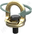


The new Crosby SL150M Slide-Loc™ provides features not found on standard lifting eye bolts. At the center of the new design is the patent pending locking mechanism that slides to lock the bolt for faster installation, then slides back to make ready for lifting — without the need for tools.
Features
- When compared to respective size eye bolts, the Crosby SL150M Slide-Loc™:
- Has a larger eye opening for easy access.
- Utilizes a bail that swivels 360˚ to keep load aligned with the sling leg, and maintains full WLL at any angle.
- Fatigue Rated® to 20,000 cycles at 1-1/2 times the WLL.
- The patent pending locking mechanism provides quicker installation, without the need for tools.
- QUIC-CHECK® mark indicates if the Crosby SL150M Slide-Loc™ is ready for the lift.
- Forged alloy steel and Quenched and Tempered bail provides toughness in potentially abusive field conditions.
- Meets the Machinery Directive 2006/42/EC guidelines and is marked with CE accordingly.
- Capacities from .3 to 3.0 metric tons
- Bolt sizes from 8 mm to 24 mm
- Forged Alloy Steel – Quenched and Tempered bail provides the following:
- Easily readable “Raised Lettering” showing the name Crosby or “CG” and PIC Code for material traceability.
- Greater durability providing the increased “Toughness” desired in potentially abusive field conditions.
- Larger opening than standard eye bolts.
Additional Information
- The Working Load Limit is permanently forged into each bail.
- 360˚ swivel
- Rated at 100% for 90˚ angle.
- Fatigue rated to 20,000 cycles at 1-1/2 times the Working Load Limit.
- Meets or exceeds all requirements of ASME B30.26 including identification, ductility, design factor, proof load and temperature requirements. Importantly, these bolts meet other critical performance requirements including fatigue life, impact properties and material traceability, not addressed by ASME B30.26.
- Proof Tested to 2.5 times Working Load Limit per EN1677.
- Replaceable bolts available, including longer bolts.
- 4:1 Design Factor
- Manufactured by an ISO 9001 facility
- Bolt specification for metric bolt is Grade 10.9 alloy hex head bolt to ISO 898-1.
- Bolt specification for imperial bolt is Grade 8 alloy hex head bolt to ASME B18.2.1.
- A color coded section of each Slide-Loc® bail provides a QUIC-CHECK® feature for easy identification.
- Red on the bail indicates the Slide-Loc® bail and bolt are engaged for installation.
- When the red is covered by the locking device, the Slide-Loc® is ready for lifting.
Installation and Lifting Positions - Patent Pending
Installation Position
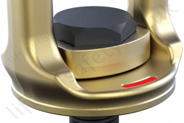
The visible red QUIC-CHECK® mark indicates that the Crosby Slide-Loc™ is ready for installation but not for lifting.
Lifting Position
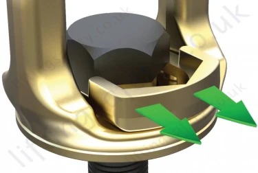
When the red QUIC-CHECK® mark is under the slide, the Crosby Slide-Loc™ is ready for lifting.
Dimensions and Specifications
Metric Sizes
| Size | Stock N°. | Working Load Limit (t) | Bolt Size - A | B (mm) | C (mm) | E (mm) | F (mm) | H (mm) | Effective Thread Projection Length - T (mm) |
| M10 | 1068515 | 0.5 | M10x1.5 x 25 | 35.5 | 53 | 28 | 8.5 | 27.8 | 14.6 |
| M12 | 1068524 | 0.75 | M12x1.75 x 30 | 42.5 | 62.6 | 33 | 10.5 | 32.9 | 18.3 |
| M16 | 1068533 | 1.5 | M16x2 x 40 | 55 | 75.7 | 37 | 13.2 | 37 | 24.5 |
| M20 | 1068542 | 2.3 | M20x2.5 x 50 | 68.8 | 91.1 | 43.9 | 16 | 43.6 | 31 |
| M24 | 1068551 | 3.0 | M24x3 x 60 | 82.5 | 110 | 52.8 | 19.2 | 52.8 | 37 |
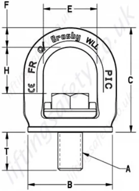
Imperial Sizes
| Size | Stock N°. | Working Load Limit (t) | Bolt Size - A | B (in.) | C (in.) | E (in.) | F (in.) | H (in.) | Effective Thread Projection Length - T (in.) |
| 3/8" | 1068507 | 0.5 | 3/8-16 UNC X 1 | 1.4 | 2.09 | 1.11 | 0.33 | 1.11 | 0.6 |
| 1/2" | 1068516 | 0.75 | 1/2-13 UNC X 1 1/4 | 1.67 | 2.47 | 1.30 | 0.41 | 1.30 | 0.79 |
| 5/8" | 1068525 | 1.5 | 5/8-11 UNC X 1 5/8 | 2.17 | 2.98 | 1.46 | 0.52 | 1.46 | 1.01 |
| 3/4" | 1068534 | 2.3 | 3/4-10 UNC X 2 | 2.71 | 3.59 | 1.72 | 0.63 | 1.72 | 1.26 |
| 7/8" | 1068543 | 2.3 | 7/8-9 UNC X 2 1/2 | 2.71 | 3.61 | 1.72 | 0.63 | 1.72 | 1.23 |
| 1" | 1068552 | 3 | 1-8 UNC X 3 | 3.25 | 4.33 | 2.08 | 0.76 | 1.93 | 1.59 |

The new Crosby SL150M Slide-Loc™ provides features not found on standard lifting eye bolts. At the center of the new design is the patent pending locking mechanism that slides to lock the bolt for faster installation, then slides back to make ready for lifting — without the need for tools.
Features
- When compared to respective size eye bolts, the Crosby SL150M Slide-Loc™:
- Has a larger eye opening for easy access.
- Utilizes a bail that swivels 360˚ to keep load aligned with the sling leg, and maintains full WLL at any angle.
- Fatigue Rated® to 20,000 cycles at 1-1/2 times the WLL.
- The patent pending locking mechanism provides quicker installation, without the need for tools.
- QUIC-CHECK® mark indicates if the Crosby SL150M Slide-Loc™ is ready for the lift.
- Forged alloy steel and Quenched and Tempered bail provides toughness in potentially abusive field conditions.
- Meets the Machinery Directive 2006/42/EC guidelines and is marked with CE accordingly.
- Capacities from .3 to 3.0 metric tons
- Bolt sizes from 8 mm to 24 mm
- Forged Alloy Steel – Quenched and Tempered bail provides the following:
- Easily readable “Raised Lettering” showing the name Crosby or “CG” and PIC Code for material traceability.
- Greater durability providing the increased “Toughness” desired in potentially abusive field conditions.
- Larger opening than standard eye bolts.
Additional Information
- The Working Load Limit is permanently forged into each bail.
- 360˚ swivel
- Rated at 100% for 90˚ angle.
- Fatigue rated to 20,000 cycles at 1-1/2 times the Working Load Limit.
- Meets or exceeds all requirements of ASME B30.26 including identification, ductility, design factor, proof load and temperature requirements. Importantly, these bolts meet other critical performance requirements including fatigue life, impact properties and material traceability, not addressed by ASME B30.26.
- Proof Tested to 2.5 times Working Load Limit per EN1677.
- Replaceable bolts available, including longer bolts.
- 4:1 Design Factor
- Manufactured by an ISO 9001 facility
- Bolt specification for metric bolt is Grade 10.9 alloy hex head bolt to ISO 898-1.
- Bolt specification for imperial bolt is Grade 8 alloy hex head bolt to ASME B18.2.1.
- A color coded section of each Slide-Loc® bail provides a QUIC-CHECK® feature for easy identification.
- Red on the bail indicates the Slide-Loc® bail and bolt are engaged for installation.
- When the red is covered by the locking device, the Slide-Loc® is ready for lifting.
Installation and Lifting Positions - Patent Pending
Installation Position

The visible red QUIC-CHECK® mark indicates that the Crosby Slide-Loc™ is ready for installation but not for lifting.
Lifting Position

When the red QUIC-CHECK® mark is under the slide, the Crosby Slide-Loc™ is ready for lifting.
Dimensions and Specifications
Metric Sizes
| Size | Stock N°. | Working Load Limit (t) | Bolt Size - A | B (mm) | C (mm) | E (mm) | F (mm) | H (mm) | Effective Thread Projection Length - T (mm) |
| M10 | 1068515 | 0.5 | M10x1.5 x 25 | 35.5 | 53 | 28 | 8.5 | 27.8 | 14.6 |
| M12 | 1068524 | 0.75 | M12x1.75 x 30 | 42.5 | 62.6 | 33 | 10.5 | 32.9 | 18.3 |
| M16 | 1068533 | 1.5 | M16x2 x 40 | 55 | 75.7 | 37 | 13.2 | 37 | 24.5 |
| M20 | 1068542 | 2.3 | M20x2.5 x 50 | 68.8 | 91.1 | 43.9 | 16 | 43.6 | 31 |
| M24 | 1068551 | 3.0 | M24x3 x 60 | 82.5 | 110 | 52.8 | 19.2 | 52.8 | 37 |

Imperial Sizes
| Size | Stock N°. | Working Load Limit (t) | Bolt Size - A | B (in.) | C (in.) | E (in.) | F (in.) | H (in.) | Effective Thread Projection Length - T (in.) |
| 3/8" | 1068507 | 0.5 | 3/8-16 UNC X 1 | 1.4 | 2.09 | 1.11 | 0.33 | 1.11 | 0.6 |
| 1/2" | 1068516 | 0.75 | 1/2-13 UNC X 1 1/4 | 1.67 | 2.47 | 1.30 | 0.41 | 1.30 | 0.79 |
| 5/8" | 1068525 | 1.5 | 5/8-11 UNC X 1 5/8 | 2.17 | 2.98 | 1.46 | 0.52 | 1.46 | 1.01 |
| 3/4" | 1068534 | 2.3 | 3/4-10 UNC X 2 | 2.71 | 3.59 | 1.72 | 0.63 | 1.72 | 1.26 |
| 7/8" | 1068543 | 2.3 | 7/8-9 UNC X 2 1/2 | 2.71 | 3.61 | 1.72 | 0.63 | 1.72 | 1.23 |
| 1" | 1068552 | 3 | 1-8 UNC X 3 | 3.25 | 4.33 | 2.08 | 0.76 | 1.93 | 1.59 |

You May Also Like
Contact Us About This Product
If you wish to receive a quote for this product, please use the tab above, this form is for general enquiries regarding this product only.
You can also Request a Quote using the Quote tab above!
You can easily add more than one item to the Quote Request. This is highly recommended as we will be able to suit your needs much more efficiently.
