-
Lifting Equipment

Lifting Equipment
- Chain Hoists
-
Wire Rope Hoists & Winches
- Hand Operated Wire Rope Winches and Hoists
- Cable Pullers / Hoists, Wire Rope Manual Operation
- Electric Winches and Hoists, AC (Mains Powered)
- Scaffold Hoists & Accessories
- Overhead Wire Rope Crane Hoists
- Hydraulic Wire Rope Winches & Hoists
- Pneumatic Wire Rope Air Winches / Hoists (Lifting and Pulling)
- Vehicle Mounted Winches
- Tractel Wire Rope & Accessories
-
General Lifting Equipment
- Soft Lifting Slings
- Lifting Chain Slings
- Wire Rope Slings & Assemblies
- Lifting Shackles
- Eye Bolts and Nuts
- Weld-on Lifting Eyes and Lashing Points
- Lifting & Pulling Clamps
- Lifting Beams & Spreader Beams
- Precast Concrete Lifting
- Lifting Magnets, Permanent, Battery Electric and Manual
- Beam Trolleys and Crane Bridges, Push, Geared & Electric
- Equipment Identification Tags
-
Rigging Equipment
- Master Ring & Load Suspension Eyes
- Lifting & Rigging Hooks
- Turnbuckles & Rigging Screws
- Wire Rope Accessories and Fittings
- Snatch Blocks, Sheave Blocks and Crane Pulley Blocks
- Pulley Sheaves
- Lifting & Rigging Swivels - Eye, Hook & Shackle
- Load Restraint Equipment
- General Rigging Accessories
- Crosby Lifting & Rigging
-
Cranes & Gantry Systems
- Portable Davit Arms
- Swing Jib Cranes - Installed Floor & Wall Cranes
- Portable/Mobile Free-standing Swing Jib Cranes
- Aluminium Gantry Cranes
- Steel Gantry Cranes
- Fixed Steel Gantry Systems
- Shearlegs, Tripods & Quadpods
- Overhead Crane Systems
- Portable Shop-Floor/Workshop/Garage Cranes
- Counterbalance Floor, Workshop Cranes
- Scaffolding Runway Beam Systems
-
Material Handling & Jacking Equipment
- Machinery & Load Moving Skates
- Hydraulic Cylinders & Pumps
- Lifting Jacks
- Manhole Cover Lifters
- Hydraulic Pull Cylinders
- Hand Operated Pallet Trucks, Pump Trucks
- Stacker Trucks, Materials Lifts, Manual and Electric
- Genie and Counterbalance Materials Lifters
- Scissor Lift Tables
- Drum Handling Equipment
- Crane Forks
- Load Weighing Equipment - Load Cells
- Tool Spring Balancers / Load Balancers
- Platform Trucks & Trolleys
-
Forklift Truck Attachment
- Fork Mounted Man Riding Baskets
- Environment & Waste Handling Attachments
- Fork Lift Truck Mounted Drum Handling Attachments
- Fork Mounted Jib and Hook Attachments
- Fork Truck Booms & Tines
- Stainless Steel Forklift Attachments
- Forklift Truck Fork Extensions
- Multi Fork Attachments
- Fork Truck Scoop Attachments
- Big Bag Fork Truck Attachment
- Closed Base Coil Support Attachments
- Forklift Fork Protection Sleeves
- Snow Plough Fork Lift Truck Attachments
- Other Forklift Truck & Telehandler Attachments
- Specialist Lifting Equipment
- Access and Safety Related
- Workshop and Shop Floor
- Screwjacks & Actuators
-
Height Safety

Height Safety Equipment
-
Fall Arrest and Height Safety Harnesses
- General Use Harnesses EN361
- Work Positioning Harnesses EN361 & EN358
- Rope Access Harnesses
- Rescue Harnesses EN1497 & EN361
- Ladies & Childrens Harnesses
- Hi Vis Jacket/Vest Harnesses
- Welders Harnesses
- ATEX (Anti-Static) Harnesses
- Linesman Harnesses
- Oil Derrick Harnesses
- Sport Climbing Harnesses
- Tree Surgeon Positioning Harnesses
- Sit and Chest Harnesses. EN361 EN356 & EN831
- Work Positioning & Restraint Belts EN358
- Fall Arrest, Restraint and Positioning Lanyards
- Height Safety and Fall Arrest Kits
- Inertia Reels and Retrieval Blocks
-
Confined Space and Rescue Systems
- Xtirpa Confined Space Davit Arm Systems and Components
- Sala Advanced Davit Arm Systems and Components
- Genesi Confined Space Systems
- Abtech Man-riding, Fall Arrest and Rescue Davits and Components
- Man-riding Hoists & Rescue Winches
- Fall Arrest & Rescue Tripods
- Fall Arrest Davit Arms & Posts for Working at Height
-
Fall Arrest & Man-riding Systems
- Manriding Systems, Baskets and Chairs
- Mobile Fall Arrest Gantries, Systems & Steps
- Rope Guided Fall Arresters (Steel & Synthetic Rope)
- Temporary Horizontal Fall Arrest Lifelines
- Vertical Fall Arrest Systems Permanently Installed
- Horizontal Fall Arrest Systems Permanently Installed
- Manriding Baskets Fork Truck and Overhead Crane
- Tank Side Entry and Vehicle Fall Arrest Systems
- Suspension Seats / Bosuns Chair Working at Height
- Collective Fall Arrest Systems
- Man-Riding Sheave Blocks
- Anchorage Devices
- Karabiners & Connectors
- Rescue, Evacuation & Rope Access
-
General Height Safety Gear
- Height Safety Accessories
- Industrial & Climbing Height Safety Helmets
- Synthetic Height Safety Rope & Anchorage Lines
- Height safety Pulley Wheels For Synthetic & Steel Wire Rope
- Black Height Safety Equipment & PPE
- Hot Work Equipment. Cutting, Grinding & Welding
- Cases, Bags, Backpacks, Holdalls. Height Safety Gear
- Telescopic Extension Pole for Height Safety Applications
- Wind Energy Height Safety Equipment
- Stainless Steel Fall Arrest Equipment
-
Fall Arrest and Height Safety Harnesses
- Home
- About Us
-
Contact
Get In Touch
- Home/
- Lifting Equipment/
- General Industrial Lifting Equipment/
- Lifting Magnets, Permanent, Battery Electric and Manual/
- Permanent Lifting Magnets; Mechanical (Lever) Operation (No power needed) to 5000kg/
- Yale "TPM" Permanent Lifting Magnet - Range from 100kg to 3000kg
Yale "TPM" Permanent Lifting Magnet - Range from 100kg to 3000kg
Yale permanent lifting magnets for round or flat materials handling.
Yale TPM / PLM-1011

The Yale TPM series of load lifting magnets are available in the following capacities; 100kg, 300kg, 500kg, 800kg, 1000kg & 2000kg.
Yale TPM load lifting magnets are ideal tools for easy, quick and thus economical transport of heavy objects made from ferro-magnetic material.
Capacities and Reductions
The selection of the appropriate magnet model should be made under consideration of the varying conditions of the contact surface, kind of material alloy and plate thickness (see below and 'Capacity Reductions' Tab above).
Note: In order to achieve a maximum capacity, the contact surface should be bright and free from dirt, oil, grease, scale, corrosion, paint etc.
Magnet Features
- Typical operating areas are workshops and warehouses, loading and unloading of machines as well as construction of jigs and fixtures.
- Small dimensions of the units provide a wide number of additional applications.
- The load is not affected mechanically which allows lifting of flat as well as round material.
- The efficient magnet body provides strong lifting capacity at low dead weight.
- The permanent magnets do not require electric energy and will present only minor residual magnetism after switching off.
- Switching ON and OFF operations are easily accomplished by turning a locking lever.
- In activated condition the hand lever will be safely locked and thus prevent unintended demagnetising.
Dimensions & Specifications
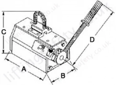
| Model | Flat Material | Round Materials | Test Load (kg) | Dimensions (mm) | Weight (kg) | |||||||
| Capacity Max ** | Thickness min. (mm) | Length max. (mm) | Capacity Max ** | dia. (mm) | Length max. (mm) | A | B | C | D | |||
| TPM 0.1 | 100 | 14 | 2000 | 50 | 40-300 | 2000 | 300 | 122 | 69 | 185 | 160 | 6.3 |
| TPM 0.3 | 300 | 20 | 2500 | 150 | 60-300 | 2500 | 900 | 192 | 95 | 225 | 250 | 13.5 |
| TPM 0.5 | 500 | 24 | 3000 | 250 | 60-400 | 3000 | 1500 | 232 | 120 | 270 | 250 | 27.5 |
| TPM 0.8 | 800 | 34 | 3500 | 400 | 60-400 | 3500 | 2400 | 302 | 154 | 320 | 450 | 52 |
| TPM 1.0 | 1000 | 40 | 3500 | 500 | 80-400 | 3500 | 3000 | 332 | 154 | 320 | 450 | 57 |
| TPM 2.0 | 2000 | 55 | 3500 | 1000 | 100-400 | 3500 | 6000 | 392 | 196 | 420 | 450 | 125 |
| TPM 3.0 | 3000 | 65 | 3500 | 1500 | 200-500 | 3500 | 9000 | 497 | 220 | 453 | 600 | 195 |

**Maximum lifting capacity is achieved by using mild steels with the noted minimum thickness.
Mild steel st37 - Fe 360 to BS EN 10 025 1990 (DIN 17100).
Capacity Reductions
| Reduction of Capacity | % of Capacity |
| Temperature ≤ 60°C | 100 % |
| Humidity ≤ 80% | 100 % |
| St 52 | 95 % |
| Alloy Steel | 80 % |
| High Carbon Steel | 70 % |
| Cast Iron | 45 % |
| Nickel | 45 % |
| Austenitic, Stainless Steel | 0 % |
| Brass | 0 % |
| Aluminium | 0 % |


Factors that reduce the magnetic clamping force:
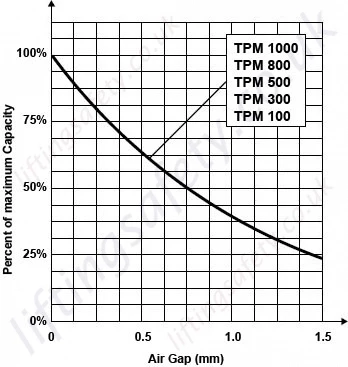
Air gap: High magnetic forces created by the TPM allow the magnet to clamp components through the air gap. However, air gaps will reduce the magnetic performance as they provide a barrier between the contact surfaces. Air gaps occur in a number of different ways, such as paint, dust, and heavy mill scale. Poorly machined surfaces also constitute an air gap. Please down rate the magnet capacity in accordance with the adhesive force/air gap diagram below.
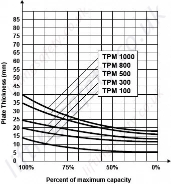
Material thickness: If the TPM is used to lift plates thinner than the recommended minimum thickness, the clamping forces will be significantly reduced. Performance curves can be identified in conjunction with the adhesive force/flat thickness diagram below.
Contact area: Full lifting capacity can only be achieved when the magnet has full contact area with the component being lifted. If the contact surface has holes in or is uneven, then the performance will be affected accordingly. Always carry out a trial lift in these circumstances to establish correct lifting before transporting the load.
Material type: Certain materials have different abilities to carry magnetism. For materials other than mild steel, a reduction factor must be applied in order to calculate the effective clamping force.
Typical values:
Ferrous alloy steels 0.8
High carbon steels 0.7
Cast iron 0.55
Examples of reduced SWL:
Mild steel 500g
Cast iron 500kg x 0.55 = 275kgs

Pricing
Availability
Usually 1-2 Working Days - 1pm cut-off
The Yale TPM series of load lifting magnets are available in the following capacities; 100kg, 300kg, 500kg, 800kg, 1000kg & 2000kg.
Yale TPM load lifting magnets are ideal tools for easy, quick and thus economical transport of heavy objects made from ferro-magnetic material.
Capacities and Reductions
The selection of the appropriate magnet model should be made under consideration of the varying conditions of the contact surface, kind of material alloy and plate thickness (see below and 'Capacity Reductions' Tab above).
Note: In order to achieve a maximum capacity, the contact surface should be bright and free from dirt, oil, grease, scale, corrosion, paint etc.
Magnet Features
- Typical operating areas are workshops and warehouses, loading and unloading of machines as well as construction of jigs and fixtures.
- Small dimensions of the units provide a wide number of additional applications.
- The load is not affected mechanically which allows lifting of flat as well as round material.
- The efficient magnet body provides strong lifting capacity at low dead weight.
- The permanent magnets do not require electric energy and will present only minor residual magnetism after switching off.
- Switching ON and OFF operations are easily accomplished by turning a locking lever.
- In activated condition the hand lever will be safely locked and thus prevent unintended demagnetising.
Dimensions & Specifications
| Model | Flat Material | Round Materials | Test Load (kg) | Dimensions (mm) | Weight (kg) | |||||||
| Capacity Max ** | Thickness min. (mm) | Length max. (mm) | Capacity Max ** | dia. (mm) | Length max. (mm) | A | B | C | D | |||
| TPM 0.1 | 100 | 14 | 2000 | 50 | 40-300 | 2000 | 300 | 122 | 69 | 185 | 160 | 6.3 |
| TPM 0.3 | 300 | 20 | 2500 | 150 | 60-300 | 2500 | 900 | 192 | 95 | 225 | 250 | 13.5 |
| TPM 0.5 | 500 | 24 | 3000 | 250 | 60-400 | 3000 | 1500 | 232 | 120 | 270 | 250 | 27.5 |
| TPM 0.8 | 800 | 34 | 3500 | 400 | 60-400 | 3500 | 2400 | 302 | 154 | 320 | 450 | 52 |
| TPM 1.0 | 1000 | 40 | 3500 | 500 | 80-400 | 3500 | 3000 | 332 | 154 | 320 | 450 | 57 |
| TPM 2.0 | 2000 | 55 | 3500 | 1000 | 100-400 | 3500 | 6000 | 392 | 196 | 420 | 450 | 125 |
| TPM 3.0 | 3000 | 65 | 3500 | 1500 | 200-500 | 3500 | 9000 | 497 | 220 | 453 | 600 | 195 |

**Maximum lifting capacity is achieved by using mild steels with the noted minimum thickness.
Mild steel st37 - Fe 360 to BS EN 10 025 1990 (DIN 17100).
Capacity Reductions
| Reduction of Capacity | % of Capacity |
| Temperature ≤ 60°C | 100 % |
| Humidity ≤ 80% | 100 % |
| St 52 | 95 % |
| Alloy Steel | 80 % |
| High Carbon Steel | 70 % |
| Cast Iron | 45 % |
| Nickel | 45 % |
| Austenitic, Stainless Steel | 0 % |
| Brass | 0 % |
| Aluminium | 0 % |


Factors that reduce the magnetic clamping force:
Air gap: High magnetic forces created by the TPM allow the magnet to clamp components through the air gap. However, air gaps will reduce the magnetic performance as they provide a barrier between the contact surfaces. Air gaps occur in a number of different ways, such as paint, dust, and heavy mill scale. Poorly machined surfaces also constitute an air gap. Please down rate the magnet capacity in accordance with the adhesive force/air gap diagram below.
Material thickness: If the TPM is used to lift plates thinner than the recommended minimum thickness, the clamping forces will be significantly reduced. Performance curves can be identified in conjunction with the adhesive force/flat thickness diagram below.
Contact area: Full lifting capacity can only be achieved when the magnet has full contact area with the component being lifted. If the contact surface has holes in or is uneven, then the performance will be affected accordingly. Always carry out a trial lift in these circumstances to establish correct lifting before transporting the load.
Material type: Certain materials have different abilities to carry magnetism. For materials other than mild steel, a reduction factor must be applied in order to calculate the effective clamping force.
Typical values:
Ferrous alloy steels 0.8
High carbon steels 0.7
Cast iron 0.55
Examples of reduced SWL:
Mild steel 500g
Cast iron 500kg x 0.55 = 275kgs

You May Also Like
Contact Us About This Product
If you wish to receive a quote for this product, please use the tab above, this form is for general enquiries regarding this product only.
You can also Request a Quote using the Quote tab above!
You can easily add more than one item to the Quote Request. This is highly recommended as we will be able to suit your needs much more efficiently.


