-
Lifting Equipment

Lifting Equipment
- Chain Hoists
-
Wire Rope Hoists & Winches
- Hand Operated Wire Rope Winches and Hoists
- Cable Pullers / Hoists, Wire Rope Manual Operation
- Electric Winches and Hoists, AC (Mains Powered)
- Scaffold Hoists & Accessories
- Overhead Wire Rope Crane Hoists
- Hydraulic Wire Rope Winches & Hoists
- Pneumatic Wire Rope Air Winches / Hoists (Lifting and Pulling)
- Vehicle Mounted Winches
- Tractel Wire Rope & Accessories
-
General Lifting Equipment
- Soft Lifting Slings
- Lifting Chain Slings
- Wire Rope Slings & Assemblies
- Lifting Shackles
- Eye Bolts and Nuts
- Weld-on Lifting Eyes and Lashing Points
- Lifting & Pulling Clamps
- Lifting Beams & Spreader Beams
- Precast Concrete Lifting
- Lifting Magnets, Permanent, Battery Electric and Manual
- Runway Beam Monorail Crane Trolleys, Push, Geared & Electric
- Equipment Identification Tags
-
Rigging Equipment
- Master Ring & Load Suspension Eyes
- Lifting & Rigging Hooks
- Turnbuckles & Rigging Screws
- Wire Rope Accessories and Fittings
- Snatch Blocks, Sheave Blocks and Crane Pulley Blocks
- Pulley Sheaves
- Lifting & Rigging Swivels - Eye, Hook & Shackle
- Load Restraint Equipment
- General Rigging Accessories
- Crosby Lifting & Rigging
-
Cranes & Gantry Systems
- Portable Davit Arms
- Swing Jib Cranes - Installed Floor & Wall Cranes
- Portable/Mobile Free-standing Swing Jib Cranes
- Aluminium Gantry Cranes
- Steel Gantry Cranes
- Fixed Steel Gantry Systems
- Shearlegs, Tripods & Quadpods
- Overhead Crane Systems
- Portable Shop-Floor/Workshop/Garage Cranes
- Counterbalance Floor, Workshop Cranes
- Scaffolding Runway Beam Systems
-
Material Handling & Jacking Equipment
- Machinery & Load Moving Skates
- Hydraulic Cylinders & Pumps
- Lifting Jacks
- Manhole Cover Lifters
- Hydraulic Pull Cylinders
- Hand Operated Pallet Trucks, Pump Trucks
- Stacker Trucks, Materials Lifts, Manual and Electric
- Genie and Counterbalance Materials Lifters
- Scissor Lift Tables
- Drum Handling Equipment
- Crane Forks
- Load Weighing Equipment - Load Cells
- Tool Spring Balancers / Load Balancers
- Platform Trucks & Trolleys
-
Forklift Truck Attachment
- Fork Mounted Man Riding Baskets
- Environment & Waste Handling Attachments
- Fork Lift Truck Mounted Drum Handling Attachments
- Fork Mounted Jib and Hook Attachments
- Fork Truck Booms & Tines
- Stainless Steel Forklift Attachments
- Forklift Truck Fork Extensions
- Multi Fork Attachments
- Fork Truck Scoop Attachments
- Big Bag Fork Truck Attachment
- Closed Base Coil Support Attachments
- Forklift Fork Protection Sleeves
- Snow Plough Fork Lift Truck Attachments
- Other Forklift Truck & Telehandler Attachments
- Specialist Lifting Equipment
- Access and Safety Related
- Workshop and Shop Floor
- Screwjacks & Actuators
-
Height Safety

Height Safety Equipment
-
Fall Arrest and Height Safety Harnesses
- General Use Harnesses EN361
- Work Positioning Harnesses EN361 & EN358
- Rope Access Harnesses
- Rescue Harnesses EN1497 & EN361
- Ladies & Childrens Harnesses
- Hi Vis Jacket/Vest Harnesses
- Welders Harnesses
- ATEX (Anti-Static) Harnesses
- Linesman Harnesses
- Oil Derrick Harnesses
- Sport Climbing Harnesses
- Tree Surgeon Positioning Harnesses
- Sit and Chest Harnesses. EN361 EN356 & EN831
- Work Positioning & Restraint Belts EN358
- Fall Arrest, Restraint and Positioning Lanyards
- Height Safety and Fall Arrest Kits
- Inertia Reels and Retrieval Blocks
-
Confined Space and Rescue Systems
- Xtirpa Confined Space Davit Arm Systems and Components
- Sala Advanced Davit Arm Systems and Components
- Genesi Confined Space Systems
- Abtech Man-riding, Fall Arrest and Rescue Davits and Components
- Man-riding Hoists & Rescue Winches
- Fall Arrest & Rescue Tripods
- Fall Arrest Davit Arms & Posts for Working at Height
-
Fall Arrest & Man-riding Systems
- Manriding Systems, Baskets and Chairs
- Mobile Fall Arrest Gantries, Systems & Steps
- Rope Guided Fall Arresters (Steel & Synthetic Rope)
- Temporary Horizontal Fall Arrest Lifelines
- Vertical Fall Arrest Systems Permanently Installed
- Horizontal Fall Arrest Systems Permanently Installed
- Manriding Baskets Fork Truck and Overhead Crane
- Tank Side Entry and Vehicle Fall Arrest Systems
- Suspension Seats / Bosuns Chair Working at Height
- Collective Fall Arrest Systems
- Man-Riding Sheave Blocks
- Anchorage Devices
- Karabiners & Connectors
- Rescue, Evacuation & Rope Access
-
General Height Safety Gear
- Height Safety Accessories
- Industrial & Climbing Height Safety Helmets
- Synthetic Height Safety Rope & Anchorage Lines
- Height safety Pulley Wheels For Synthetic & Steel Wire Rope
- Black Height Safety Equipment & PPE
- Hot Work Equipment. Cutting, Grinding & Welding
- Cases, Bags, Backpacks, Holdalls. Height Safety Gear
- Telescopic Extension Pole for Height Safety Applications
- Wind Energy Height Safety Equipment
- Stainless Steel Fall Arrest Equipment
-
Fall Arrest and Height Safety Harnesses
- Home
- About Us
-
Contact
Get In Touch
- Home/
- Lifting Equipment/
- Cranes; Mobile, Portable and Fixed/
- Swing Jib Cranes - Installed Floor & Wall Cranes/
- Column Mounted (Post), Free Standing Swing Jib Cranes/
- Donati 'I' Profile Under Braced Jib Crane - upto 2000kg SWL
Donati 'I' Profile Under Braced Jib Crane - upto 2000kg SWL
290° Manual Slew 'I' Profile Free Standing Swing Jib Crane with Underbraced Arm.
GBA T3 / PA-977
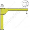
The manually rotated jib cranes are available for lifting capacities from 125 kg to 2000 kg and jibs from 2m to 8m. The Donati jib cranes are designed and manufactured according to the ISO A5 classification. The possible configuration are: - GBA, floor mounted jib crane with square column characterized by a jib rotating angle of 300. The crane jib can be supplied in three different solution: - "T" cantilever version, for lifting capacities from 63kg to 2000kg and outreach from 2m to 5m. The arm is made using a laminated I-beam form: the hoist-carrying trolley run on the lower flange of the I-beam. The girder is self-supporting and cantilevered, so it has no support tie rods and it is directly integral with, via suitable reinforcement, the rotation tube. This version allows the optimum use of the available space at a height due to the absence of tie rods and allows the maximum use of the hook path. The arm allows the addition of either electric or hand-pushed trolley.
“T” cantilever version:
- For lifting capacities from 63kg to 2000kg
- Jibs from 2 m to 5 m
- The arm is made using a laminate T-beam form: the hoist-carrying trolley run on the lower flange of the T-beam.
- The girder is self-supporting and cantilevered, so it has no support staybolts, and it is directly integral with, via suitable reinforcements, the rotation tube.
- This version allows the optimum use of the available space at a height due to the absence of staybolts and allows the maximum use of the hook run. The arm allows the addition of electrical or mechanical push-trolleys.
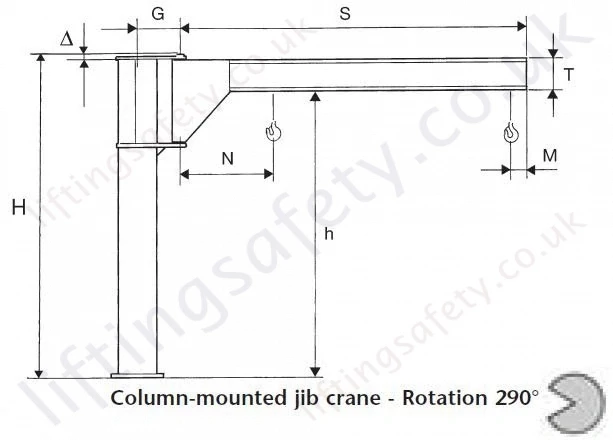
Dimensions
| Lifting Capacity (KG) |
Arm (S) M |
Size of Jib Crane Bracket |
Column |
Total Height H (M) |
Type | Under Beam h |
G | M | N | T | Δ | Weight Crane (KG) |
Column by m |
| 63 | 4 | A | R | 3 | T30R40 | 2800 | 228 | 190 | 655 | 160 | 12 | 148 | 18.2 |
| 5 | A | R | 3 | T30R50 | 2800 | 228 | 190 | 715 | 160 | 12 | 164 | 18.2 | |
| 125 | 2 | A | R | 3 | T30R20 | 2800 | 228 | 190 | 595 | 160 | 12 | 116 | 18.2 |
| 3 | A | R | 3 | T30R30 | 2800 | 228 | 190 | 655 | 160 | 12 | 132 | 18.2 | |
| 4 | B | S | 3 | T30S40 | 2760 | 274 | 190 | 725 | 200 | 12 | 200 | 22.8 | |
| 5 | B | S | 3 | T30S50 | 2760 | 274 | 190 | 785 | 200 | 12 | 222 | 22.8 | |
| 250 | 2 | B | S | 3 | T30S20 | 2760 | 274 | 190 | 665 | 200 | 12 | 156 | 22.8 |
| 3 | B | S | 3 | T30S30 | 2760 | 274 | 190 | 725 | 200 | 12 | 178 | 22.8 | |
| 4 | C | T | 3.5 | T35T40 | 3212 | 323 | 190 | 800 | 240 | 17 | 320 | 35 | |
| 5 | C | T | 3.5 | T35T50 | 3212 | 323 | 190 | 860 | 240 | 17 | 351 | 35 | |
| 6 | D | U | 190 | 1000 | 300 | ||||||||
| 6 | E | V | 4 | T40V62 | 3640 | 443 | 190 | 1065 | 300 | 20 | 705 | 64 | |
| 7 | E | V | 4 | T40V72 | 3580 | 443 | 190 | 1135 | 360 | 20 | 852 | 64 | |
| 500 | 2 | C | T | 3.5 | T35T20 | 3212 | 323 | 190 | 740 | 240 | 17 | 260 | 35 |
| 3 | C | T | 3.5 | T35T30 | 3212 | 323 | 190 | 800 | 240 | 17 | 290 | 35 | |
| 4 | D | U | 3.5 | T35U40 | 3152 | 386 | 190 | 880 | 300 | 17 | 430 | 43.5 | |
| 5 | D | U | 3.5 | T35U50 | 3152 | 386 | 190 | 940 | 300 | 17 | 472 | 43.5 | |
| 6 | E | V | 4 | T40V65 | 3580 | 443 | 190 | 1140 | 360 | 20 | 779 | 64 | |
| 6 | F | Z | 4 | T40Z62 | 3580 | 513 | 190 | 1140 | 360 | 20 | 864 | 75.2 | |
| 7 | E | V | 4 | T40V75 | 3540 | 443 | 190 | 1270 | 400 | 20 | 893 | 64 | |
| 7 | F | Z | 4 | T40Z72 | 3540 | 513 | 190 | 1270 | 400 | 20 | 978 | 75.2 | |
| 1000 | 2 | D | U | 3.5 | T35U20 | 3152 | 386 | 190 | 820 | 300 | 17 | 346 | 43.5 |
| 3 | D | U | 3.5 | T35U30 | 3152 | 386 | 190 | 880 | 300 | 17 | 388 | 43.5 | |
| 4 | E | V | 4 | T40V40 | 3580 | 443 | 190 | 945 | 360 | 20 | 678 | 64 | |
| 5 | E | V | 4 | T40V50 | 3580 | 443 | 190 | 1005 | 360 | 20 | 735 | 64 | |
| 6 | F | Z | 4 | T40Z65 | 3540 | 513 | 190 | 1190 | 400 | 20 | 912 | 75.2 | |
| 7 | F | Z | 190 | 1270 | 450 | ||||||||
| 1600 | 6 | F | Z | 190 | 1270 | 450 | |||||||
| 2000 | 2 | E | V | 4 | T40V20 | 3580 | 443 | 210 | 900 | 360 | 20 | 564 | 64 |
| 3 | E | V | 4 | T40V30 | 3580 | 443 | 210 | 960 | 360 | 20 | 621 | 64 | |
| 4 | F | Z | 4 | T40Z40 | 3540 | 513 | 210 | 1070 | 400 | 20 | 780 | 75.2 | |
| 5 | F | Z | 210 | 1220 | 450 |
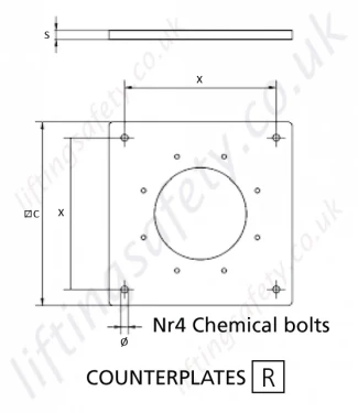
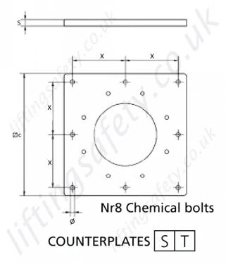
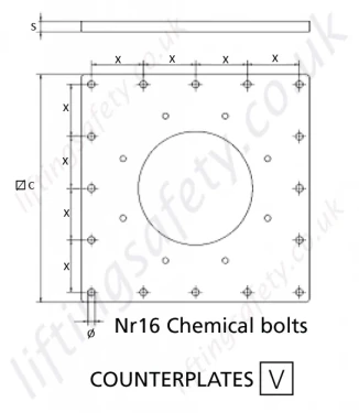
Oversized Base Plate/CounterPlate (Bolting To Existing Floor)
This is designed to spread the load when bolted to a suitable existing concrete floor. Refer below for manufacturers minimum recommended floor thickness.
| Counter Plate Type | R | S | T | U | V | Z | |
|
Counterplate Dimensions (mm) |
C | 400 | 450 | 500 | 600 | 800 | 950 |
| S | 20 | 25 | 25 | 30 | 35 | 45 | |
| X | 330 | 195 | 220 | 180 | 182 | 220 | |
| Y / Y1 | - | - | - | - | - | 240 / 248 | |
| Nr x Dia. | 4 x 15 | 8 x 15 | 8 x 19 | 12 x 19 | 16 x 25 | 28 x 25 | |
| Counterplate Weight (kg) | 20 | 31 | 39 | 63 | 139 | 254 | |
| Maximum tilting movement allowed (kNm) | 11,8 | 20,7 | 31,2 | 56,7 | 107,3 | 164 | |
| Type of concrete of the floor: Class Rck minimum (kg/cm2) | C250 | C250 | C250 | C250 | C250 | C250 | |
| Minimum thickness of floor block (mm) | 140 | 170 | 170 | 220 | 220 | 220 | |
| Diameter of hole in the floor (mm) | 14 | 14 | 18 | 18 | 24 | 24 | |
| Depth of the hole of the concrete in the floor (mm) | 110 | 110 | 125 | 125 | 170 | 170 | |
| Clamping torques of the bolts (Nm) | 40 | 40 | 80 | 80 | 150 | 150 | |
| Project resistance of traction of one bolt (kN) | 25,3 | 25,3 | 40 | 40 | 74,6 | 74,6 |
The fixing of the column using chemical bolts, needs a scrupulous check of suitability in relation to the type of support flooring.
The suitability checks are the responsibility of the user and must be carried out by expert, qualified technicians who will evaluate the feasibility and formally undertake the relative responsibilities.

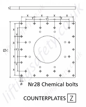
Base Plate Specifications
Note: The foundation frame with logbolts, used in the column-mounted version for fixing the column itself to the foundation plinth is supplied on request.
| Size of Jib Crane | R | S | T | U | V | Z |
| Base Plate and Foundation Frame (mm) | ||||||
| C | 205 | 258 | 296 | 372 | 435 | 515 |
| P | 275 | 340 | 380 | 475 | 555 | 660 |
| S1 | 15 | 15 | 15 | 20 | 20 | 25 |
| S2 | 8 | 8 | 8 | 8 | 8 | 8 |
| X | 247 | 305 | 345 | 432 | 506 | 599 |
| Y | 103 | 126 | 143 | 179 | 210 | 248 |
| Ø | 268 | 330 | 373 | 468 | 548 | 648 |
| R | 88 | 104 | 116 | 145 | 165 | 197 |
| Ø1 | 16 | 20 | 20 | 25 | 29 | 35 |
| Ø2 | 13 | 17 | 17 | 21 | 25 | 31 |
| Anchorage Bolts | ||||||
| ØT | M12 | M16 | M16 | M20 | M24 | M30 |
| LT | 400 | 450 | 450 | 550 | 600 | 700 |
| ST | 40 | 45 | 45 | 55 | 60 | 75 |
| Clamping Couples (Nm) | 45 | 105 | 105 | 200 | 350 | 680 |
| Frame/Bolts Weight (kg) | 5 | 10 | 11 | 17 | 26 | 47 |
| Foundation | ||||||
| Foundation Plinth (mm) (L) | 1200 | 1300 | 1400 | 1700 | 2000 | 2400 |
| Foundation Plinth (H) | 800 | 800 | 900 | 900 | 1100 | 1100 |
| Reaction (kN) Q1 | 3.3 | 5.7 | 10.15 | 18.4 | 28.7 | 29.35 |
| Momentum (kNm) MF | 10 | 16 | 30 | 56 | 107 | 163 |
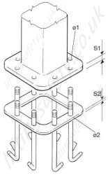
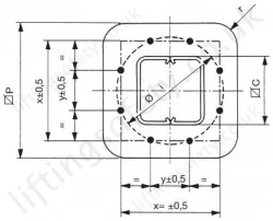
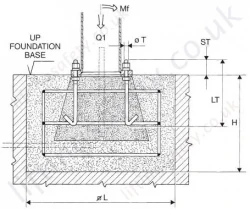
Pricing
The manually rotated jib cranes are available for lifting capacities from 125 kg to 2000 kg and jibs from 2m to 8m. The Donati jib cranes are designed and manufactured according to the ISO A5 classification. The possible configuration are: - GBA, floor mounted jib crane with square column characterized by a jib rotating angle of 300. The crane jib can be supplied in three different solution: - "T" cantilever version, for lifting capacities from 63kg to 2000kg and outreach from 2m to 5m. The arm is made using a laminated I-beam form: the hoist-carrying trolley run on the lower flange of the I-beam. The girder is self-supporting and cantilevered, so it has no support tie rods and it is directly integral with, via suitable reinforcement, the rotation tube. This version allows the optimum use of the available space at a height due to the absence of tie rods and allows the maximum use of the hook path. The arm allows the addition of either electric or hand-pushed trolley.
“T” cantilever version:
- For lifting capacities from 63kg to 2000kg
- Jibs from 2 m to 5 m
- The arm is made using a laminate T-beam form: the hoist-carrying trolley run on the lower flange of the T-beam.
- The girder is self-supporting and cantilevered, so it has no support staybolts, and it is directly integral with, via suitable reinforcements, the rotation tube.
- This version allows the optimum use of the available space at a height due to the absence of staybolts and allows the maximum use of the hook run. The arm allows the addition of electrical or mechanical push-trolleys.
Dimensions
| Lifting Capacity (KG) |
Arm (S) M |
Size of Jib Crane Bracket |
Column |
Total Height H (M) |
Type | Under Beam h |
G | M | N | T | Δ | Weight Crane (KG) |
Column by m |
| 63 | 4 | A | R | 3 | T30R40 | 2800 | 228 | 190 | 655 | 160 | 12 | 148 | 18.2 |
| 5 | A | R | 3 | T30R50 | 2800 | 228 | 190 | 715 | 160 | 12 | 164 | 18.2 | |
| 125 | 2 | A | R | 3 | T30R20 | 2800 | 228 | 190 | 595 | 160 | 12 | 116 | 18.2 |
| 3 | A | R | 3 | T30R30 | 2800 | 228 | 190 | 655 | 160 | 12 | 132 | 18.2 | |
| 4 | B | S | 3 | T30S40 | 2760 | 274 | 190 | 725 | 200 | 12 | 200 | 22.8 | |
| 5 | B | S | 3 | T30S50 | 2760 | 274 | 190 | 785 | 200 | 12 | 222 | 22.8 | |
| 250 | 2 | B | S | 3 | T30S20 | 2760 | 274 | 190 | 665 | 200 | 12 | 156 | 22.8 |
| 3 | B | S | 3 | T30S30 | 2760 | 274 | 190 | 725 | 200 | 12 | 178 | 22.8 | |
| 4 | C | T | 3.5 | T35T40 | 3212 | 323 | 190 | 800 | 240 | 17 | 320 | 35 | |
| 5 | C | T | 3.5 | T35T50 | 3212 | 323 | 190 | 860 | 240 | 17 | 351 | 35 | |
| 6 | D | U | 190 | 1000 | 300 | ||||||||
| 6 | E | V | 4 | T40V62 | 3640 | 443 | 190 | 1065 | 300 | 20 | 705 | 64 | |
| 7 | E | V | 4 | T40V72 | 3580 | 443 | 190 | 1135 | 360 | 20 | 852 | 64 | |
| 500 | 2 | C | T | 3.5 | T35T20 | 3212 | 323 | 190 | 740 | 240 | 17 | 260 | 35 |
| 3 | C | T | 3.5 | T35T30 | 3212 | 323 | 190 | 800 | 240 | 17 | 290 | 35 | |
| 4 | D | U | 3.5 | T35U40 | 3152 | 386 | 190 | 880 | 300 | 17 | 430 | 43.5 | |
| 5 | D | U | 3.5 | T35U50 | 3152 | 386 | 190 | 940 | 300 | 17 | 472 | 43.5 | |
| 6 | E | V | 4 | T40V65 | 3580 | 443 | 190 | 1140 | 360 | 20 | 779 | 64 | |
| 6 | F | Z | 4 | T40Z62 | 3580 | 513 | 190 | 1140 | 360 | 20 | 864 | 75.2 | |
| 7 | E | V | 4 | T40V75 | 3540 | 443 | 190 | 1270 | 400 | 20 | 893 | 64 | |
| 7 | F | Z | 4 | T40Z72 | 3540 | 513 | 190 | 1270 | 400 | 20 | 978 | 75.2 | |
| 1000 | 2 | D | U | 3.5 | T35U20 | 3152 | 386 | 190 | 820 | 300 | 17 | 346 | 43.5 |
| 3 | D | U | 3.5 | T35U30 | 3152 | 386 | 190 | 880 | 300 | 17 | 388 | 43.5 | |
| 4 | E | V | 4 | T40V40 | 3580 | 443 | 190 | 945 | 360 | 20 | 678 | 64 | |
| 5 | E | V | 4 | T40V50 | 3580 | 443 | 190 | 1005 | 360 | 20 | 735 | 64 | |
| 6 | F | Z | 4 | T40Z65 | 3540 | 513 | 190 | 1190 | 400 | 20 | 912 | 75.2 | |
| 7 | F | Z | 190 | 1270 | 450 | ||||||||
| 1600 | 6 | F | Z | 190 | 1270 | 450 | |||||||
| 2000 | 2 | E | V | 4 | T40V20 | 3580 | 443 | 210 | 900 | 360 | 20 | 564 | 64 |
| 3 | E | V | 4 | T40V30 | 3580 | 443 | 210 | 960 | 360 | 20 | 621 | 64 | |
| 4 | F | Z | 4 | T40Z40 | 3540 | 513 | 210 | 1070 | 400 | 20 | 780 | 75.2 | |
| 5 | F | Z | 210 | 1220 | 450 |

Oversized Base Plate/CounterPlate (Bolting To Existing Floor)
This is designed to spread the load when bolted to a suitable existing concrete floor. Refer below for manufacturers minimum recommended floor thickness.
| Counter Plate Type | R | S | T | U | V | Z | |
|
Counterplate Dimensions (mm) |
C | 400 | 450 | 500 | 600 | 800 | 950 |
| S | 20 | 25 | 25 | 30 | 35 | 45 | |
| X | 330 | 195 | 220 | 180 | 182 | 220 | |
| Y / Y1 | - | - | - | - | - | 240 / 248 | |
| Nr x Dia. | 4 x 15 | 8 x 15 | 8 x 19 | 12 x 19 | 16 x 25 | 28 x 25 | |
| Counterplate Weight (kg) | 20 | 31 | 39 | 63 | 139 | 254 | |
| Maximum tilting movement allowed (kNm) | 11,8 | 20,7 | 31,2 | 56,7 | 107,3 | 164 | |
| Type of concrete of the floor: Class Rck minimum (kg/cm2) | C250 | C250 | C250 | C250 | C250 | C250 | |
| Minimum thickness of floor block (mm) | 140 | 170 | 170 | 220 | 220 | 220 | |
| Diameter of hole in the floor (mm) | 14 | 14 | 18 | 18 | 24 | 24 | |
| Depth of the hole of the concrete in the floor (mm) | 110 | 110 | 125 | 125 | 170 | 170 | |
| Clamping torques of the bolts (Nm) | 40 | 40 | 80 | 80 | 150 | 150 | |
| Project resistance of traction of one bolt (kN) | 25,3 | 25,3 | 40 | 40 | 74,6 | 74,6 |
The fixing of the column using chemical bolts, needs a scrupulous check of suitability in relation to the type of support flooring.
The suitability checks are the responsibility of the user and must be carried out by expert, qualified technicians who will evaluate the feasibility and formally undertake the relative responsibilities.


Base Plate Specifications
Note: The foundation frame with logbolts, used in the column-mounted version for fixing the column itself to the foundation plinth is supplied on request.
| Size of Jib Crane | R | S | T | U | V | Z |
| Base Plate and Foundation Frame (mm) | ||||||
| C | 205 | 258 | 296 | 372 | 435 | 515 |
| P | 275 | 340 | 380 | 475 | 555 | 660 |
| S1 | 15 | 15 | 15 | 20 | 20 | 25 |
| S2 | 8 | 8 | 8 | 8 | 8 | 8 |
| X | 247 | 305 | 345 | 432 | 506 | 599 |
| Y | 103 | 126 | 143 | 179 | 210 | 248 |
| Ø | 268 | 330 | 373 | 468 | 548 | 648 |
| R | 88 | 104 | 116 | 145 | 165 | 197 |
| Ø1 | 16 | 20 | 20 | 25 | 29 | 35 |
| Ø2 | 13 | 17 | 17 | 21 | 25 | 31 |
| Anchorage Bolts | ||||||
| ØT | M12 | M16 | M16 | M20 | M24 | M30 |
| LT | 400 | 450 | 450 | 550 | 600 | 700 |
| ST | 40 | 45 | 45 | 55 | 60 | 75 |
| Clamping Couples (Nm) | 45 | 105 | 105 | 200 | 350 | 680 |
| Frame/Bolts Weight (kg) | 5 | 10 | 11 | 17 | 26 | 47 |
| Foundation | ||||||
| Foundation Plinth (mm) (L) | 1200 | 1300 | 1400 | 1700 | 2000 | 2400 |
| Foundation Plinth (H) | 800 | 800 | 900 | 900 | 1100 | 1100 |
| Reaction (kN) Q1 | 3.3 | 5.7 | 10.15 | 18.4 | 28.7 | 29.35 |
| Momentum (kNm) MF | 10 | 16 | 30 | 56 | 107 | 163 |


You May Also Like
Contact Us About This Product
If you wish to receive a quote for this product, please use the tab above, this form is for general enquiries regarding this product only.
You can also Request a Quote using the Quote tab above!
You can easily add more than one item to the Quote Request. This is highly recommended as we will be able to suit your needs much more efficiently.
